Suzuki Grand Vitara JB416 / JB420 / JB419. Manual - part 219
 

  Index      Suzuki     Suzuki Grand Vitara JB416 / JB420 / JB419 - service repair manual 2007 year


Search            


Content   ..  217  218  219  220   ..


Suzuki Grand Vitara JB416 / JB420 / JB419. Manual - part 219


2B-20 Front Suspension: 

Specifications

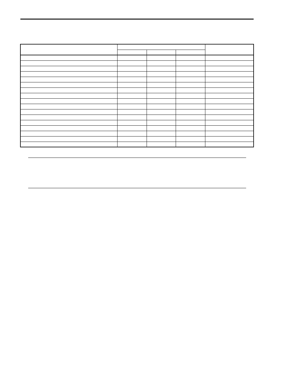
Tightening Torque Specifications

S6JB0A2207001

NOTE
The specified tightening torque is also described in the following.
“Front Suspension Construction: ”
“Front Strut Assembly Components: ”
“Front Wheel Hub Assembly and Steering Knuckle Components: ”
“Front Suspension Frame, Stabilizer Bar and/or Bushings Components: ”


Reference:
For the tightening torque of fastener not specified in this section, refer to “Fastener Information in Section 0A”.

Fastening part

Tightening torque

Note

N

m

kgf-m

lb-ft

Tie-rod end lock nut

65

6.5 

47.0

)

Strut bracket nut

135

13.5 

98.0

)

 / )

Brake hose mounting bolt

25

2.5 

18.0

)

Stabilizer joint nut

60

6.0 

43.5

)

 / )

Wheel speed sensor harness clamp bolt

11

1.1 

8.0

)

Strut support nut

50

5.0 

36.5

)

Wheel nut

100

10.0 

72.5

)

 / ) / ) / )

Strut nut

70

7.0 

51.0

)

Wheel hub housing bolt

50

5.0 

36.5

)

Caliper carrier bolt

85

8.5 

61.5

)

Drive shaft nut

220

22.0 

159.5

)

Suspension arm ball joint nut

55

5.5 

40.0

)

Wheel speed sensor bolt

11

1.1 

8.0

)

Suspension control arm nut

135

13.5 

98.0

)

Stabilizer bar mounting bracket bolt

50

5.0 

36.5

)

Suspension frame mounting bolt

135

13.5 

98.0

)

Engine front body side mounting nut

55

5.5 

40.0

)

Front Suspension:  2B-21

Special Tools and Equipment

Recommended Service Material

S6JB0A2208001

NOTE
Required service material is also described in the following.
“Front Suspension Construction: ”
“Front Strut Assembly Components: ”
“Front Suspension Frame, Stabilizer Bar and/or Bushings Components: ”


Special Tool

S6JB0A2208002

Material

SUZUKI recommended product or Specification

Note

Grease

SUZUKI Super Grease A

P/No.: 99000–25010

)

09900–00411

09900–00414

Hexagon bit socket

Hexagon bit (6 mm)

)

 / )

)

 / )

09913–75821

09941–56510

Bearing installer attachment

Socket wrench (19 mm)

)

 / )

)

 / )

09943–25010

09945–55410

Spring compressor

Bushing installer

)

)

 / )

2C-1 Rear Suspension: 

Suspension

Rear Suspension

General Description

Rear Suspension Construction

S6JB0A2301001

Rear Wheel Alignment Construction

S6JB0A2301002

Among factors for rear wheel alignment, only toe and camber setting can be adjusted. Caster can’t be adjusted. 
Therefore, should caster be out of specification due to the damage caused by hazardous road conditions or collision, 
whether the damage is in body or in suspension should be determined and damaged body should be repaired or 
damaged suspension should be replaced.

4

5

(b)

(b)

A

B

[A]

3

8

1

2

(a)

(f)

(e)

(b)

(b)

(b)

[B]

6

8

9

(b)

(b)

(b)

(g)

(f)

(b)

(d)

(c)

1

2

3

(b)

I6JB0A230001-03

[A]: View A

4. Control rod

9. Lower Arm

: 50 N

⋅m (5.0 kgf-m, 36.5 lb-ft)

[B]: View B

5. Trailing rod

: 105 N

⋅m (10.5 kgf-m, 76.0 lb-ft)

: 60 N

⋅m (6.0 kgf-m, 43.5 lb-ft)

1. Rear shock absorber

6. Rear brake drum

: 135 N

⋅m (13.5 kgf-m, 98.0 lb-ft)

: 90 N

⋅m (9.0 kgf-m, 65.0 lb-ft)

2. Rear suspension knuckle

7. Rear drive shaft

: 55 N

⋅m (5.5 kgf-m, 40.0 lb-ft)

: Do not reuse.

3. Rear suspension frame

8. Upper Arm

: 220 N

⋅m (22.0 kgf-m, 159.5 lb-ft)

: If bolt and/or nut is reused, apply 

engine oil to thread, bearing and 
trunk surface.

Rear Suspension:  2C-2

Repair Instructions

Rear Wheel Alignment Inspection and 
Adjustment

S6JB0A2306001

Among factors for rear wheel alignment, only toe and 
camber setting can be adjusted.
Caster can’t be adjusted. Therefore, should caster be 
out of specification due to the damage caused by 
hazardous road conditions or collision, whether the 
damage is in body or in suspension should be 
determined and damaged body should be repaired or 
damaged suspension should be replaced.

Toe and Camber Inspection and Adjustment
Preparation for toe and camber inspection and 
adjustment.
• Place vehicle in non-loaded state on level floor.
• Set steering wheel in straight state.
• Check that inflation pressure of each tire is adjusted 

properly and disc wheel is free from deflection.

• Check that each suspension part is free from bend, 

dent, wear or damage in any other form.

• Check that ground clearance at the right and left is 

just about the same.

NOTE
To prevent possible incorrect reading of toe, 
camber or caster, vehicle front and rear end 
must be moved up and down and forward 
and rearward a few times before inspection.


Inspection
Toe Inspection
Measure toe with toe-in gauge (1).
Toe should be within following specifications.

Toe
IN 6.0 

± 2.0 mm (0.2362 ± 0.0787 in.)

If toe is out of the specification, adjust toe properly.

Camber Inspection
Measure camber with camber tester.
Camber should be within following specifications.

Camber
–1

° 15’ ± 30’

If camber is out of the specification, adjust camber 
properly.

Adjustment
Control rod adjustment

1) Loosen right and left control rod mount nuts (1).

2) Adjust toe and camber to satisfy the specification by 

turning right and left control rod inner bolts (cam 
bolts) (1) with the same amount.

NOTE
When bolt is turned a-direction, camber 
becomes “+” and toe becomes “IN”. When 
bolt is turned b-direction, camber becomes 
“–” and toe becomes “OUT”.


3) After adjustment, tighten right and left nuts to 

specified torque while holding cam bolt with another 
wrench to prevent it from turning.

Tightening torque
Control rod mount nut:  135 N·m (13.5 kgf-m, 
98.0 lb-ft)

I2RH01230057-01

[A]: Right side

2. Control rod

[B]: Left side

1

I5JB0A230002-01

a

b

a

b

[A]

[B]

1

1

2

2

I5JB0A230003-01


Content   ..  217  218  219  220   ..