Suzuki Grand Vitara JB416 / JB420 / JB419. Manual - part 205
 

  Index      Suzuki     Suzuki Grand Vitara JB416 / JB420 / JB419 - service repair manual 2007 year


Search            


Content   ..  203  204  205  206   ..


Suzuki Grand Vitara JB416 / JB420 / JB419. Manual - part 205


1J-10 Charging System: For Petrol Engine Model

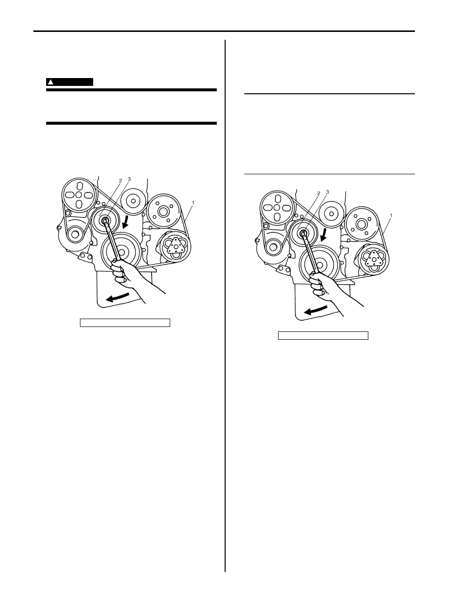
Water Pump and Generator Drive Belt Removal 
and Installation (For J20 Engine)

S6JB0A1A16006

Removal

WARNING

!


Disconnect negative (–) cable at battery 
before removing and installing generator 
belt.


1) Loosen tensioner by turning the tensioner pulley (2) 

clockwise.

2) While holding the tensioner and belt loose, remove 

generator belt (1).

Installation

1) Loosen tensioner by turning the tensioner pulley (2) 

clockwise.

2) While holding the tensioner, install generator belt (1).

NOTE

• Make sure that the belt fits each pulley’s 

groove properly.

• After installing generator belt, make sure 

that tension indicator is within standard 
range referring to “Water Pump and 
Generator Drive Belt On-Vehicle Inspection 
(For J20 Engine): For Petrol Engine 
Model”.


3. Tensioner pulley bolt

I3TR011A4001-01

3. Tensioner pulley bolt

I3TR011A4001-01

Charging System: For Petrol Engine Model 1J-11

Generator Dismounting and Remounting

S6JB0A1A16007

[A]

[B]

(a)

(b)

(c)

(b)

(c)

7

1

8

2

9

6

4

8

(a)

3

1

7

2

9

6

5

3

(c)

(c)

I5JB0A1A0003-02

[A]: For M16 Engine

4. Generator adjusting bolt (For M16 Engine)

9. Generator

[B]: For J20 Engine

5. Generator mounting bolt (For J20 Engine)

: 7.0 N

⋅m (0.7 kgf-m, 5.0 lb-ft)

1. “B” terminal wire 

6. Generator pivot bolt

: 52.5 N

⋅m (5.25 kgf-m, 38.0 lb-ft)

2. coupler

7. “B” terminal nut

: 25 N

⋅m (2.5 kgf-m, 18.5 lb-ft)

3. Water pump and generator drive belt

8. Generator bracket bolt

1J-12 Charging System: For Petrol Engine Model

Dismounting

1) Disconnect negative (–) cable at battery.
2) Disconnect MAF sensor coupler (For J20 Engine).
3) Remove air cleaner case and air cleaner outlet hose (For J20 Engine).
4) Disconnect generator lead wire (“B” terminal wire) and coupler from generator.
5) Remove generator belt. Refer to “Water Pump and Generator Drive Belt Removal and Installation (For M16 

Engine): For Petrol Engine Model” or “Water Pump and Generator Drive Belt Removal and Installation (For J20 
Engine): For Petrol Engine Model”
.

6) Remove generator drive belt adjusting bolt (For M16 Engine) and generator mounting bolt (For J20 Engine) and 

generator pivot bolt.

7) Remove generator.

Remounting

1) Mount generator on the generator bracket.
2) Tighten generator mounting bolts and generator pivot bolt as specified torque (For J20 Engine).
3) Install generator belt. Refer to “Water Pump and Generator Drive Belt Removal and Installation (For M16 Engine): 

For Petrol Engine Model” or “Water Pump and Generator Drive Belt Removal and Installation (For J20 Engine): 
For Petrol Engine Model”
.

4) Connect “B” terminal wire and coupler to generator.
5) Install air cleaner case and air cleaner outlet hose (For J20 Engine).
6) Connect MAF sensor coupler (For J20 Engine).
7) Connect negative (–) cable at battery.

Generator Components

S6JB0A1A16008

12

11

13

14

(a)

(b)

(c)

(d)

1

2

3

4

5

6

7

8

9

10

15

16

I4RS0B1A0007-01

1. Pulley nut

6. Drive end bearing

11. Rear housing

16. “B” terminal nut

2. Pulley

7. Bearing retainer

12. Rectifier

: 118 N

⋅m (11.8 kgf-m, 85.5 lb-ft)

3. Front housing

8. Rotor

13. Regulator

: 4.5 N

⋅m (0.45 kgf-m, 3.5 lb-ft)

4. Stator

9. Rear end bearing

14. Brush

: 3.5 N

⋅m (0.35 kgf-m, 2.5 lb-ft)

5. Frame bolt

10. Retainer screw

15. “B” terminal

: 8.0 N

⋅m (0.8 kgf-m, 6.0 lb-ft)

Charging System: For Petrol Engine Model 1J-13

Generator Inspection

S6JB0A1A16009

Rotor
• Using ohmmeter, connect positive terminal to “FR” terminal and connect negative terminal to “B” terminal of 

generator, check that continuity between “B” terminal and “FR” terminal. If there is no continuity, replace rotor or 
regulator.

• Using ohmmeter, check for continuity between slip rings of rotor. If there is no continuity, replace rotor (1).

Resistance between slip rings of rotor 
1.7 – 2.0 

• Using ohmmeter, check that there is no continuity between slip ring and rotor core. If there is continuity, replace 

rotor (1).

• Check slip rings for roughness or scoring. If rough or scored, replace rotor.

I5JB0A1A0012-01

IYSQ011A0035-01

IYSQ011A0036-01


Content   ..  203  204  205  206   ..