Suzuki Grand Vitara JB416 / JB420 / JB419. Manual - part 138
 

  Index      Suzuki     Suzuki Grand Vitara JB416 / JB420 / JB419 - service repair manual 2007 year


Search            


Content   ..  136  137  138  139   ..


Suzuki Grand Vitara JB416 / JB420 / JB419. Manual - part 138


1D-78 Engine Mechanical: For J20 Engine

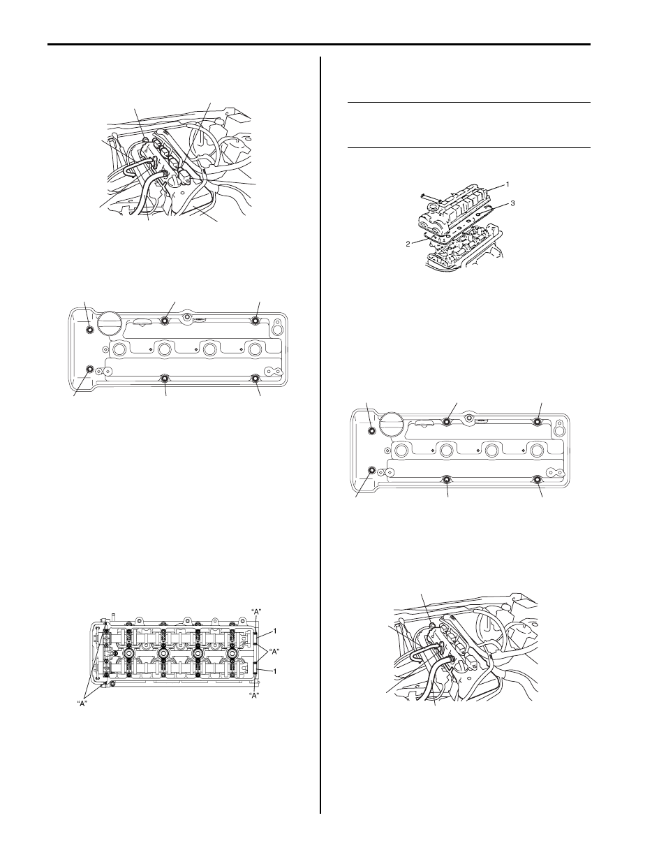
7) Disconnect breather hose (2) and PCV hose (3) from 

cylinder head cover (7).

8) Remove PCV valve from cylinder head cover.
9) Remove cylinder head cover nuts in such order as 

indicated in the figure.

Installation

1) Install PCV valve to cylinder head cover referring to 

“PCV Valve Removal and Installation: For Petrol 
Engine Model in Section 1B”.

2) Remove oil, old sealant and dust from sealing 

surfaces on cylinder head and cover.

3) Install new cylinder head side seals (1) to cylinder 

head.

4) Apply sealant “A” to cylinder head sealing surface 

area as shown in figure.

“A”:  Water tight sealant 99000–31250 (SUZUKI 
Bond No.1207F)

5) Install new O-rings (3) and new cylinder head cover 

gasket (2) to cylinder head cover (1).

NOTE
Be sure to check each of these parts for 
deterioration or any damage before 
installation and replace if found defective.


6) Install cylinder head cover to cylinder head.

7) Tighten cylinder head cover nuts in such order as 

indicated in the figure a little at a time till they are 
tightened to specified torque.
• Use new seal washers.

Tightening torque
Cylinder head cover nut (a):  11 N·m (1.1 kgf-m, 
8.0 lb-ft)

8) Install oil level gauge (1).
9) Connect CMP sensor coupler (4).

10) Connect breather hose (2) and PCV hose (3) to 

cylinder head cover.

11) Install ignition coils referring to “Ignition Coil 

Assembly (Including ignitor) Removal and 
Installation: For Petrol Engine Model in Section 1H”
.

12) Install engine cover.
13) Connect negative cable at battery.

1

4

7

5

3

6

2

I5JB0A142012-02

“2”

“6”

“4”

“3”

“5”

“1”

I5JB0A142013-01

I5JB0A142067-01

I5JB0A142068-02

“5”, (a)

“1”, (a)

“3”, (a)

“4”, (a)

“2”, (a)

“6”, (a)

I5JB0A142014-01

4

3

1

2

I5JB0A142015-01

Engine Mechanical: For J20 Engine 1D-79

Engine Mountings Components

S6JB0A1426010

(a)

9

(a)

7

(a)

7

(a)

(a)

9

(a)

1

2

1

3

5

6

(a)

(a)

(a)

8

(a)

8

4

10

11

3

1

10

3

11

1

[A]

[C]

[B]

12

12

I6JB0A142001-01

[A]: Type A

4. Engine rear mounting member

10. Heat protector panel

[B]: Type B

5. Engine rear mounting

11. Exhaust pipe No.1 bracket

[C]: View [A], [B]

6. Engine splash cover

12. Exhaust pipe No.1

1. Engine front mounting

7. Engine front mounting nut

: 55 N

⋅m (5.5 kgf-m, 40.0 lb-ft)

2. Engine front mounting right bracket

8. Engine rear mounting member bolt

3. Engine front mounting left bracket

9. Engine front mounting bracket bolt

1D-80 Engine Mechanical: For J20 Engine

Engine Assembly Removal and Installation

S6JB0A1426011

Removal

1) Relieve fuel pressure according to “Fuel Pressure 

Relief Procedure: For Petrol Engine Model in 
Section 1G”.

2) Disconnect negative cable at battery.
3) Drain engine oil referring to “Engine Oil and Filter 

Change (Petrol Engine Model) in Section 0B”.

4) Drain transmission oil referring to “Manual 

Transmission Oil Change: For Petrol Engine Model 
in Section 5B”.

5) Drain A/T fluid referring to “A/T Fluid Change in 

Section 5A”.

6) Drain coolant referring to “Cooling System Draining: 

For Petrol Engine Model in Section 1F”.

7) Remove Air cleaner case referring to “Air Cleaner 

Assembly Removal and Installation: For J20 
Engine”.

8) Remove water pump and generator drive belt 

referring to “Water Pump and Generator Drive Belt 
Removal and Installation (For J20 Engine): For 
Petrol Engine Model in Section 1J”.

9) Disconnect the following electric wires:

• MAP sensor (1)
• ECT sensor (2)
• EGR valve (3)
• CMP sensor (4)
• EVAP canister purge valve (5)
• Ignition coil assembly (6)
• Injectors (7)
• HO2S  (8)
• A/F sensor (9)
• Engine oil pressure switch (10)
• CKP sensor (11)
• Back up light switch (For M/T model) (12)
• Generator (13)
• Starting motor (14)
• Ground terminal
• Magnet clutch switch of A/C compressor (if 

equipped) (15)

• P/S pump (16)
• Electric throttle body (17)
• Transfer actuator (18)
• Center differential switch (19)
• 4L/N switch (20)
• Each wire harness clamps 
• Input shaft speed sensor (For A/T model) (26)
• Output shaft speed sensor (For A/T model) (27)
• Solenoid valve (For A/T model) (28)
• Transmission range sensor (For A/T model) (29)

10) Disconnect the following hoses: 

• Brake booster hose (21) from intake manifold
• Radiator inlet and outlet hoses (22) from each 

pipe

• Heater inlet and outlet hoses (23) from each pipe
• Fuel hoses (24) from fuel pipes
• Purge hose (25) from purge valve
• Clutch oil pipe from transmission front case (For 

M/T model) 

• A/T fluid cooler hoses from radiator (For A/T 

model) 

11) Disconnect A/T select cable from A/T (For A/T 

model).

21

1

2

3

4

5

6

7

8

9

10

11

12

13

14

15

16

17

19

20

18

22

23

24

25

26

27

28

29

I5JB0A142017-01

Engine Mechanical: For J20 Engine 1D-81

12) For M/T model, remove shift control lever referring to 

“Transmission Shift Control Lever Removal and 
Installation: For Petrol Engine Model in Section 5B”.

13) Remove exhaust No.1, No.2 and center pipes 

referring to “Exhaust System Components: For 
Petrol Engine Model in Section 1K”
.

14) Remove front and rear propeller shafts referring to 

“Propeller Shaft Removal and Installation in Section 
3D”.

15) With hose connected, detach P/S pump from its 

bracket (if equipped) referring to “P/S Pump 
Removal and Installation (J20A Engine Model) in 
Section 6C”.

CAUTION

!


Suspend removed P/S pump at a place where 
no damage will be caused during removal 
and installation of engine assembly.


16) With hose connected, detach A/C compressor from 

its bracket (if equipped) referring to “Compressor 
Assembly Removal and Installation for J20 Engine 
Model in Section 7B”.

CAUTION

!


Suspend removed A/C compressor at a place 
where no damage will be caused during 
removal and installation of engine assembly.


17) Support front suspension frame and engine rear 

mounting member using jack (2).

18) Carry out Step 1) to 12) of “Removal” under “Front 

Suspension Frame, Stabilizer Bar and/or Bushings 
Removal and Installation in Section 2B”
 in order to 
lower engine with front suspension frame.

19) Remove front suspension frame mounting bolts (1).

20) Remove engine rear mounting member bolts (1).

21) Before lowering engine, recheck to make sure all 

hoses, electric wires and cables are disconnected 
from engine.

22) Lower engine with transmission, transfer, front 

suspension frame and engine rear mounting 
member from engine compartment.

CAUTION

!


Before lowering engine, in order to avoid 
damage to A/C compressor and P/S pump, 
make clearance by rising them.


23) Disconnect transmission from engine referring to 

“Manual Transmission Assembly Dismounting and 
Remounting: For Petrol Engine Model in Section 5B” 
or “Automatic Transmission Unit Components in 
Section 5A”
, if necessary.

24) Remove engine with engine front mounting bracket 

(1) from engine front mounting (2), if necessary.

25) Remove clutch cover and clutch disk referring to 

“Clutch Cover, Clutch Disc and Flywheel Removal 
and Installation in Section 5C”, if 
necessary.

1

2

I5JB0A142018-01

1

1

I5JB0A142019-01

1

2

1

2

I5JB0A142020-01


Content   ..  136  137  138  139   ..