Suzuki Grand Vitara JB416 / JB420 / JB419. Manual - part 126
 

  Index      Suzuki     Suzuki Grand Vitara JB416 / JB420 / JB419 - service repair manual 2007 year


Search            


Content   ..  124  125  126  127   ..


Suzuki Grand Vitara JB416 / JB420 / JB419. Manual - part 126


1D-30 Engine Mechanical: For M16A Engine with VVT

9) Install timing chain with crankshaft sprocket referring 

to “Timing Chain and Chain Tensioner Removal and 
Installation: For M16A Engine with VVT”
.

10) Install timing chain cover referring to “Timing Chain 

Cover Removal and Installation: For M16A Engine 
with VVT”.

11) Check valve lashes referring to “Valve Lash 

(Clearance) Inspection: For M16A Engine with VVT”.

12) Perform Steps 3) to 8) of “Installation” of “Timing 

Chain Cover Removal and Installation: For M16A 
Engine with VVT”.

Camshaft, Tappet and Shim Inspection

S6JB0A1416021

Intake Cam Timing Sprocket Assembly
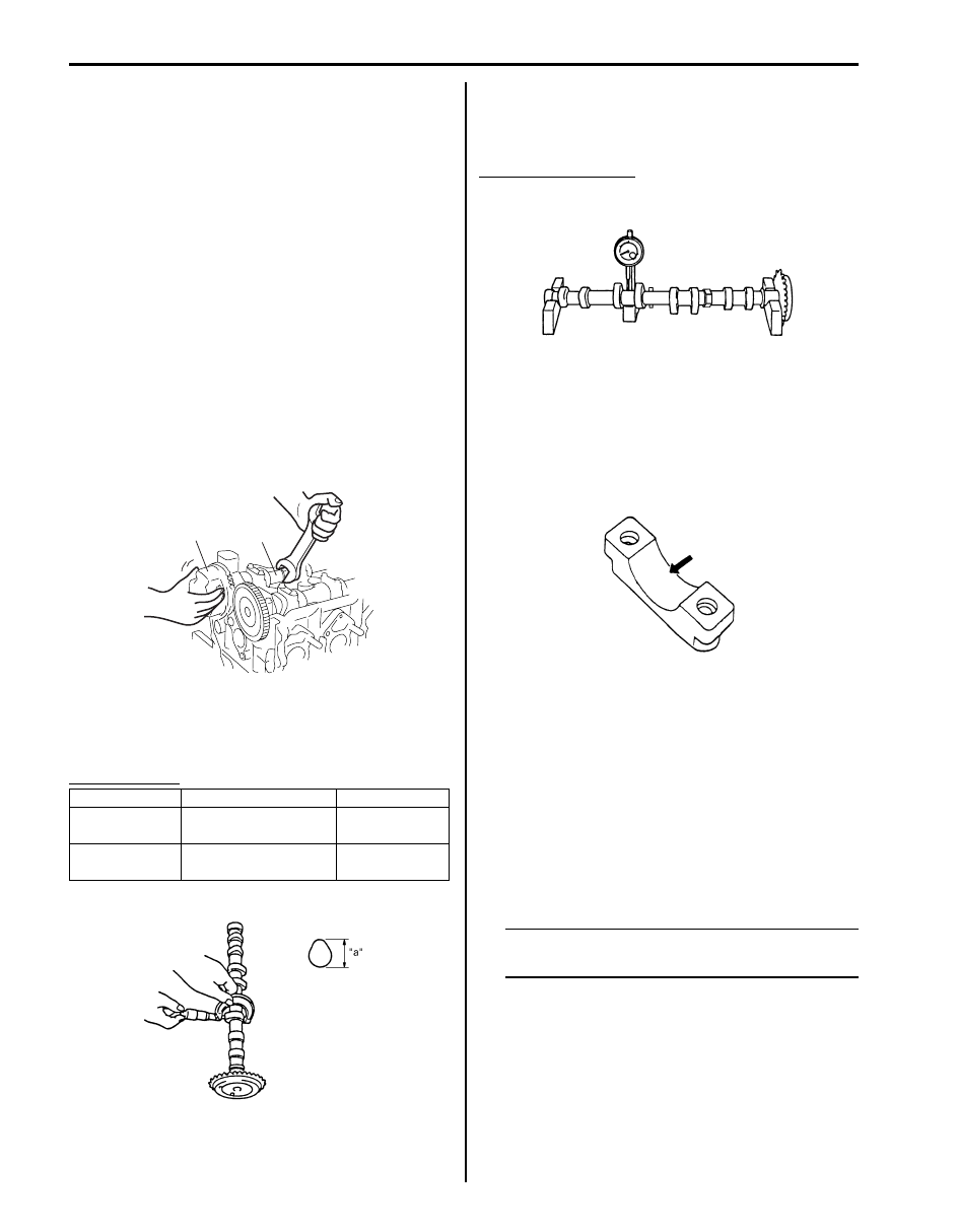
Fit intake cam timing sprocket assembly to camshaft (2) 
and hold hexagonal section of camshaft by using 
spanner or the like.
Check if sprocket (1) is not turned by hand.
If moved, replace intake cam timing sprocket assembly.

Cam Wear
Using a micrometer, measure cam height “a”. If 
measured height underruns its limit, replace camshaft.

Cam height “a”

Camshaft Runout
Set camshaft between two “V” blocks, and measure its 
runout by using a dial gauge.
If measured runout exceeds limit, replace camshaft.

Camshaft runout limit
0.10 mm (0.0039 in.)

Camshaft Journal Wear
Check camshaft journals and camshaft housings for 
pitting, scratches, wear or damage.
If any malcondition is found, replace camshaft or cylinder 
head with housing. Never replace cylinder head without 
replacing housings.

Check clearance by using gauging plastic. Checking 
procedure is as follows.

1) Clean housings and camshaft journals.
2) Remove all tappets with shims.
3) Install camshafts to cylinder head.
4) Place a piece of gauging plastic to full width of 

journal of camshaft (parallel to camshaft).

5) Install camshaft housing.
6) Tighten camshaft housing bolts in such order as 

indicated in the figure a little at a time till they are 
tightened to specified torque.

NOTE
Do not rotate camshaft while gauging plastic 
is installed.


Cam height

Standard

Limit

Intake cam

44.929 – 45.089 mm 

(1.769 – 1.775 in.)

44.80 mm 
(1.764 in.)

Exhaust cam

44.399 – 44.559 mm 

(1.748 – 1.754 in.)

44.28 mm 
(1.743 in.)

2

1

I3RH0B140043-01

I2RH0B140080-01

I2RH0B140081-01

I2RH0B140082-01

Engine Mechanical: For M16A Engine with VVT 1D-31

Tightening torque
Camshaft housing bolt (a):  11 N·m (1.1 kgf-m, 
8.0 lb-ft)

7) Remove housing, and using scale (2) on gauging 

plastic envelop, measure gauging plastic (1) width at 
its widest point.

Camshaft journal clearance

If measured camshaft journal clearance exceeds 
limit, measure journal (housing) bore and outside 
diameter of camshaft journal. Replace camshaft or 
cylinder head assembly whichever the difference 
from specification is greater.

Camshaft journal diameter [A]

Camshaft journal bearing bore [B]

Standard

Limit

Intake side 

No.1 housing

0.020 – 0.072 mm

(0.0008 – 0.0028 in.)

0.10 mm

(0.0039 in.)

Others

0.045 – 0.087 mm

(0.0018 – 0.0034 in.)

0.12 mm

(0.0047 in.)

“10” “9”

“2” “1”,(a) “6”

“5”

“14” “13”

“20”

“17”

“19”

“18”

“21”

“12” “11” “4”

“3”

“8”

“7”

“16” “15”

I3RH0B140041-01

I2RH0B140083-01

Item

Standard

Intake side No.1 housing

26.940 – 26.955 mm
(1.0606 – 1.0612 in.)

Exhaust side No.1 housing

26.934 – 26.955 mm
(1.0604 – 1.0612 in.)

Others

22.934 – 22.955 mm
(0.9029 – 0.9037 in.)

Item

Standard

Intake side No.1 housing

Exhaust side No.1 housing

27.000 – 27.021 mm 
(1.0630 – 1.0638 in.)

Others

23.000 – 23.021 mm 
(0.9055 – 0.9063 in.)

I2RH0B140084-01

1D-32 Engine Mechanical: For M16A Engine with VVT

Wear of Tappet and Shim
Check tappet and shim for pitting, scratches, or damage.
If any malcondition is found, replace.

Measure cylinder head bore and tappet outside diameter to determine cylinder head-to-tappet clearance. If clearance 
exceeds limit, replace tappet or cylinder head.

Cylinder head to tappet clearance
Standard: 0.025 – 0.066 mm (0.0010 – 0.026 in.)
Limit: 0.15 mm (0.0059 in.)

Tappet outside diameter [A]
Standard: 30.959 – 30.975 mm (1.2189 – 1.2195 in.)

Cylinder head tappet bore [B]
Standard: 31.000 – 31.025 mm (1.2205 – 1.2215 in.)

I2RH0B140085-01

I2RH0B140086-01

Engine Mechanical: For M16A Engine with VVT 1D-33

Valves and Cylinder Head Components

S6JB0A1416022

I4RS0A140015-01

1. Valve cotters

7. Exhaust valve

13. Cylinder head bolt (M8)

: Be sure to tighten cylinder head bolt (M8) after 
securing the other cylinder head bolt (M10).

2. Valve spring retainer

8. Valve guide

: Tighten 20 N

⋅m (2.0 kgf-m, 14.5 lb-ft), 40 N⋅m (4.0 

kgf-m, 29.0 lb-ft), 60

° and 60° by the specified 

procedure.

3. Valve spring

 9. Cylinder head bolt (M10)

: Check cylinder head bolt (M10), plastic deformation 
tightening bolt, for deformation referring to “Cylinder Head 
Bolt” under “Valves and Valve Guides Inspection: For 
M16A Engine with VVT”,
 if it is reused.

: 25  N

⋅m (2.5 kgf-m, 18.0 lb-ft)

4. Valve stem seal

10. Cylinder head

: Do not reuse.

5. Valve spring seat

11. Cylinder head gasket

: “TOP” mark provided on gasket comes to crankshaft 
pulley side, facing up.

: Apply engine oil to sliding surface of each part.

6. Intake valve

12. Knock pin


Content   ..  124  125  126  127   ..