Suzuki Grand Vitara JB416 / JB420 / JB419. Manual - part 124
 

  Index      Suzuki     Suzuki Grand Vitara JB416 / JB420 / JB419 - service repair manual 2007 year


Search            


Content   ..  122  123  124  125   ..


Suzuki Grand Vitara JB416 / JB420 / JB419. Manual - part 124


1D-22 Engine Mechanical: For M16A Engine with VVT

4) Remove P/S pump bracket.
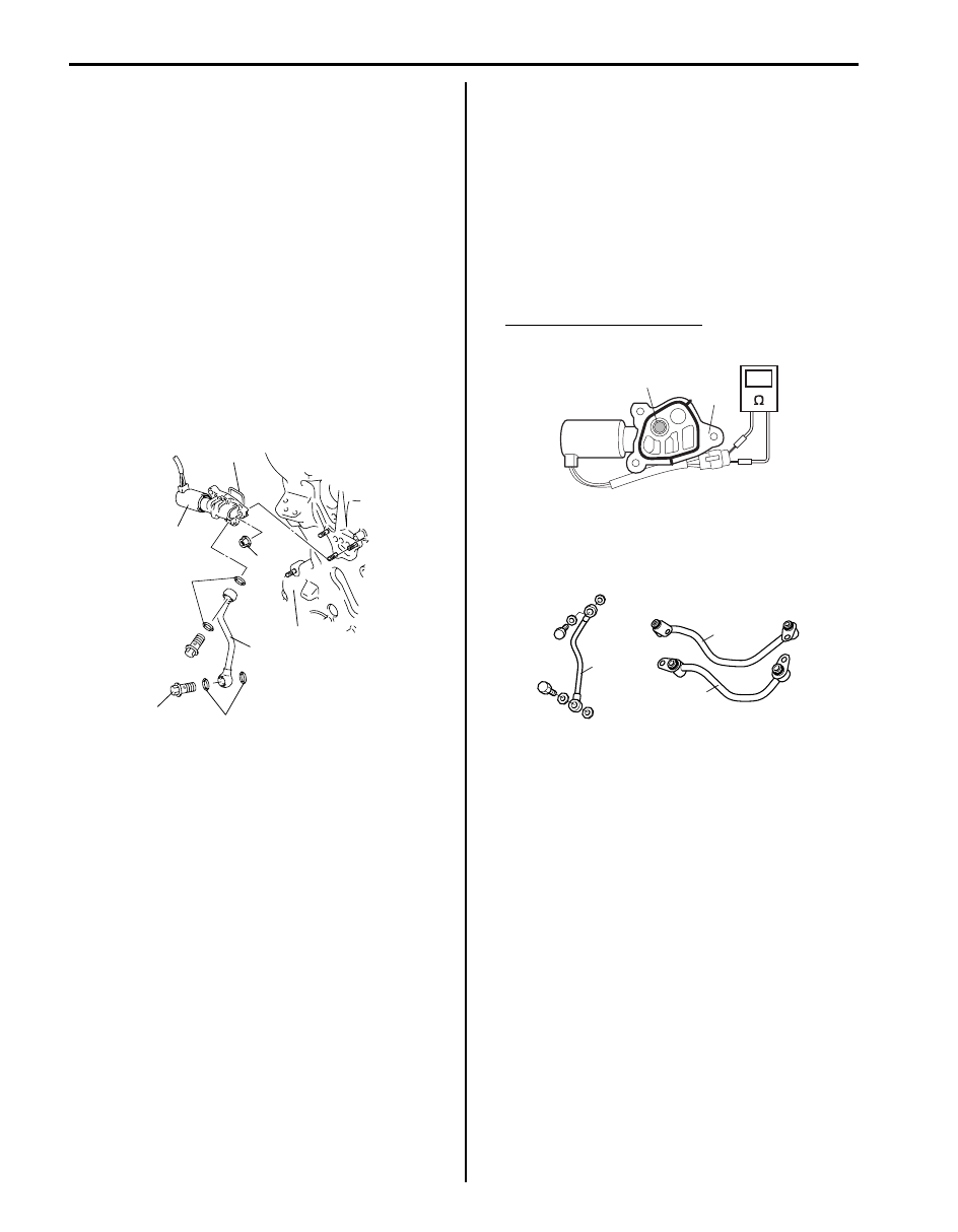
5) Remove oil gallery pipe No.1 (1) and oil control valve 

(2) from timing chain cover (3).

Installation

1) Install new O-ring (4) to oil control valve.
2) Install oil control valve to timing chain cover.

Tighten nuts to specification.

Tightening torque
Oil control valve mounting nut (a):  11 N·m (1.1 
kgf-m, 8.0 lb-ft)

3) Install oil gallery pipe No.1 with new copper washers 

(5) to timing chain cover.
Tighten bolts to specification.

Tightening torque
Oil gallery pipe No.1 bolt (b):  30 N·m (3.0 kgf-m, 
21.5 lb-ft)

4) Install P/S pump bracket.
5) Install P/S pump to its bracket referring to “P/S Pump 

Removal and Installation (M16A Engine Model) in 
Section 6C”.

6) Install P/S pump and A/C compressor drive belt 

referring to “P/S Pump and A/C Compressor (If 
Equipped) Drive Belt Removal and Installation 
(M16A Engine Model) in Section 6C”.

7) Adjust P/S pump and A/C compressor drive belt 

tension referring to “P/S Pump and A/C Compressor 
(If Equipped) Drive Belt Inspection and Adjustment 
(M16A Engine Model) in Section 6C”.

8) Refill engine with engine oil referring to “Engine Oil 

and Filter Change (Petrol Engine Model) in Section 
0B”.

Oil Control Valve Inspection

S6JB0A1416015

Oil Control Valve

1) Inspect strainer (1) and mating surface (2) of oil 

control valve for clog or damage. Clean oil control 
valve if clog or foreign matter is present on strainer 
or mating surface of oil control valve.
Replace oil control valve if its mating surface is 
damaged.

2) Check resistance between terminals of oil control 

valve.

Oil control valve resistance
6.7 – 7.7 

 (at 20 °C (68 °F))

Oil Gallery Pipe
Inspect oil gallery pipe No.1 (1), No.2 (2) and No.3 (3).
Replace if crack, deformation or clog exists.

1

5

(b)

3

(a)

2

4

5

I3RM0A140027-01

1

2

I3RM0A140028-01

1

3

2

I3RH0B140030-01

Engine Mechanical: For M16A Engine with VVT 1D-23

Timing Chain and Chain Tensioner Components

S6JB0A1416016

Timing Chain and Chain Tensioner Removal 
and Installation

S6JB0A1416017

Removal

CAUTION

!


After timing chain is removed, never turn 
crankshaft and camshafts independently 
more than its allowable turning range 
described in “Installation”.
If turned, interference may occur between 
piston and valves and valves themselves, 
and parts related to piston and valves may be 
damaged.


1) Remove timing chain cover referring to “Timing 

Chain Cover Removal and Installation: For M16A 
Engine with VVT”.

2) By turning crankshaft, align both intake and exhaust 

camshaft timing sprocket marks (1) with notches (2) 
of cylinder head respectively and align crankshaft 
sprocket key (3) with notch of cylinder block (4).

3) Remove timing chain tensioner adjuster assembly 

(5).

4) Remove timing chain tensioner (6).
5) Remove timing chain No.1 guide (7).
6) Remove timing chain (8) with crankshaft timing 

sprocket (9).

I4RS0A140012-04

1. Crankshaft timing sprocket

5. Timing chain tensioner adjuster assembly

: 25 N

⋅m (2.5 kgf-m, 18.0 lb-ft)

 2. Timing chain

: Apply engine oil.

6. Chain tensioner adjuster mounting bolt

: 11 N

⋅m (1.1 kgf-m, 8.0 lb-ft)

 3. Timing chain No.1 guide

: Apply engine oil to sliding surface.

7. Timing chain tensioner bolt

 4. Timing chain tensioner

: Apply engine oil to sliding surface.

8. Timing chain No.1 guide bolt

3

4

1

1

2

5

6

7

8

9

I3RH0B140032-01

1D-24 Engine Mechanical: For M16A Engine with VVT

Installation

CAUTION

!


After timing chain is removed, never turn 
crankshaft and camshafts independently 
more than such an extent (“a”, “b”) as shown 
in the figure.
If turned, interference may occur between 
piston and valves and valves themselves, 
and parts related to piston and valves may be 
damaged.


1) Check that match marks (1) on intake and exhaust 

camshaft timing sprockets are in match with notches 
(2) on cylinder head as shown in the figure.

2) Set key (3) and turn crankshaft to position key on 

upside of crankshaft.

3) Install timing chain by aligning dark blue plate (1) of 

timing chain and triangle mark (2) on camshaft 
timing sprocket as shown in the figure.

4) Fit crankshaft timing sprocket to timing chain by 

aligning gold plate (3) of timing chain and circle mark 
(4) on crankshaft timing sprocket. Then install 
crankshaft timing sprocket fitted with chain to 
crankshaft.

5) Apply engine oil to sliding surface of timing chain 

No.1 guide (1) and install it as shown in the figure.
Tighten guide bolts to specified torque.

Tightening torque
Timing chain No.1 guide bolt (a):  11 N·m (1.1 
kgf-m, 8.0 lb-ft)

“a”: 90

°

4. Camshaft (IN and EX) allowable turning range.

By marks on camshaft timing sprocket within 15

° from notches 

on cylinder head on both right and left.

“b”: 15

°

5. Crankshaft allowable turning range.

By key on crankshaft, within 90

° from top on both right and left.

“a”

“b”

“b”

“b”

“b”

“a”

1

1

2

4

3

5

I4RS0A140021-01

[A]: View A

1

1

2

2

3

4

Approx. 
      60˚

Approx. 
      30˚

A

[A]

I3RH0B140034-03

I2RH0B140062-01

Engine Mechanical: For M16A Engine with VVT 1D-25

6) Apply engine oil to sliding surface of chain tensioner 

(1) and install chain tensioner and spacer.
Tighten tensioner bolt to specified torque.

Tightening torque
Timing chain tensioner bolt (a):  25 N·m (2.5 kgf-
m, 18.0 lb-ft)

7) Check that match marks (1) on intake and exhaust 

camshaft timing sprockets are in match with dark 
blue plates (2) of timing chain and match mark (3) on 
crankshaft timing sprocket is in match with gold plate 
(4) of timing chain.

8) Screw in plunger (1) by turning body (2) in arrow 

direction and install a retainer (3) (wire) to hold 
plunger in place.

9) Install timing chain tensioner adjuster assembly (1) 

with a retainer (2).
Tighten adjuster bolts to specified torque and then 
remove a retainer from chain tensioner adjuster 
assembly.

Tightening torque
Timing chain tensioner adjuster bolt (a):  11 N·m 
(1.1 kgf-m, 8.0 lb-ft)

[A]: View A

I2RH0B140063-01

2

2

1

1

3

4

Approx. 
      60˚

Approx. 
      30˚

A

[A]

I3RH0B140035-03

I2RH0B140065-01

I2RH0B140066-01


Content   ..  122  123  124  125   ..