Suzuki Grand Vitara JB416 / JB420 / JB419. Manual - part 123
 

  Index      Suzuki     Suzuki Grand Vitara JB416 / JB420 / JB419 - service repair manual 2007 year


Search            


Content   ..  121  122  123  124   ..


Suzuki Grand Vitara JB416 / JB420 / JB419. Manual - part 123


1D-18 Engine Mechanical: For M16A Engine with VVT

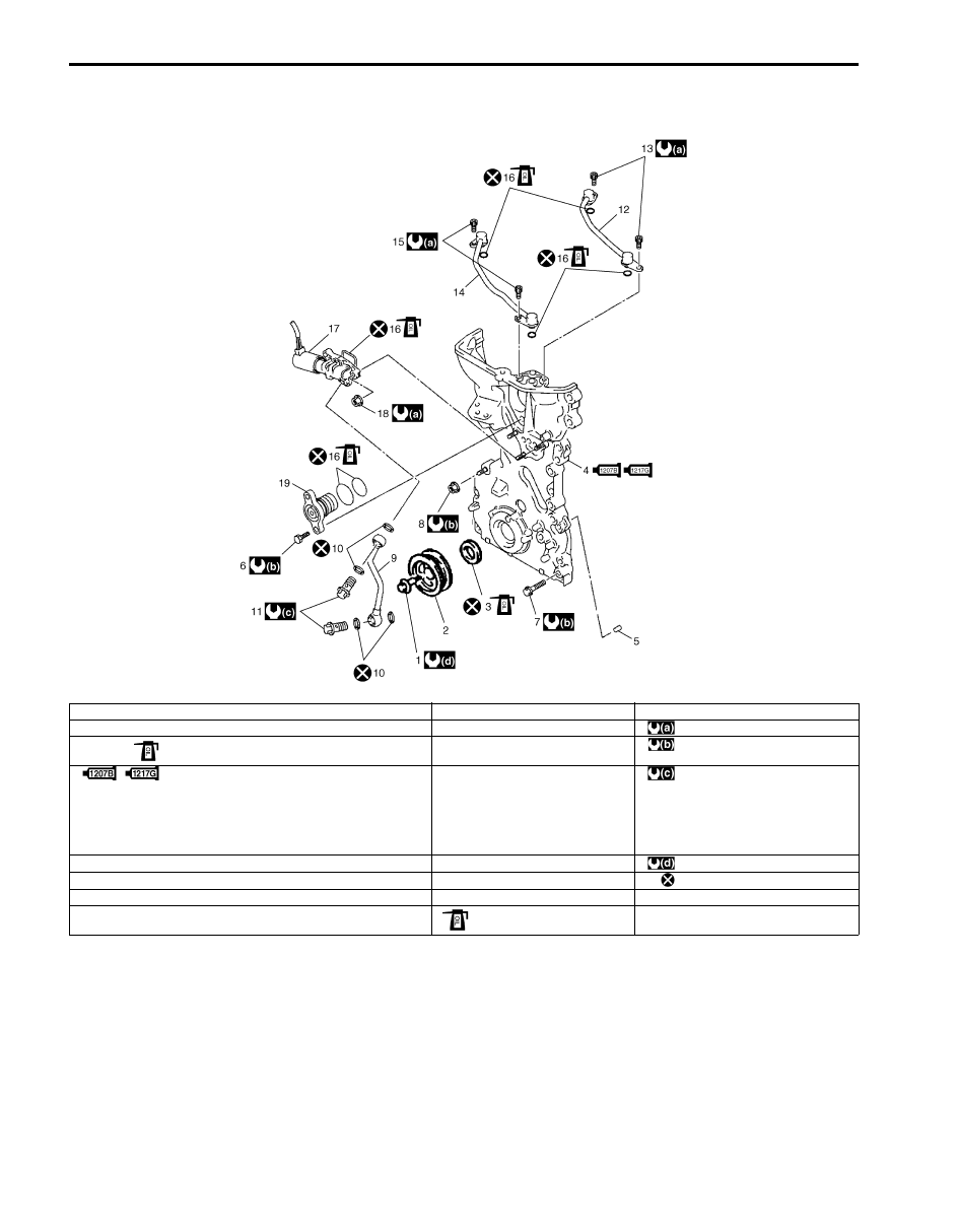
Timing Chain Cover Components

S6JB0A1416011

I5JB0A141020-02

1. Crankshaft pulley bolt

9. Oil gallery pipe No.1

17. Oil control valve

2. Crankshaft pulley

 10. Copper washer

: 11 N

⋅m (1.1 kgf-m, 8.0 lb-ft)

3. Oil seal

: Apply engine oil to oil seal lip.

11. Oil gallery pipe No.1 bolt

: 25 N

⋅m (2.5 kgf-m, 18.0 lb-ft)

4. Timing chain cover

: Apply sealant 99000-31140 to the mating surface 
of cylinder and cylinder head.
: Apply sealant 99000-31260 to the mating surface 
of timing chain cover referring to the figure of Step 4) 
of “Installation” under “Timing Chain Cover Removal 
and Installation: For M16A Engine with VVT”.

12. Oil gallery pipe No.2

: 30 N

⋅m (3.0 kgf-m, 22.0 lb-ft)

5. Pin

13. Oil gallery pipe No.2 bolt

: 150 N

⋅m (15.0 kgf-m, 108.5 lb-ft)

6. Oil control valve mounting nut

14. Oil gallery pipe No.3

: Do not reuse.

7. Timing chain cover mounting bolts

15. Oil gallery pipe No.3 bolt

8. Timing chain cover mounting nut

16. O-ring

: Apply engine oil.

Engine Mechanical: For M16A Engine with VVT 1D-19

Timing Chain Cover Removal and Installation

S6JB0A1416012

CAUTION

!


• Keep working table, tools and hands clean 

while overhauling.

• Use special care to handle aluminum parts 

so as not to damage them.

• Do not expose removed parts to dust. 

Keep them always clean.


Removal

1) Remove engine assembly from vehicle referring to 

“Engine Assembly Removal and Installation: For 
M16A Engine with VVT”.

2) Remove P/S pump and A/C compressor (if 

equipped) drive belt referring to “P/S Pump and A/C 
Compressor (If Equipped) Drive Belt Removal and 
Installation (M16A Engine Model) in Section 6C”.

3) Remove water pump and generator drive belt 

referring to “Water Pump and Generator Drive Belt 
Removal and Installation (For M16 Engine): For 
Petrol Engine Model in Section 1J”.

4) Remove crankshaft pulley bolt.

To lock crankshaft pulley (1), use special tool with it 
as shown in the figure.

Special tool
(A):  09917–68221

5) Remove crankshaft pulley (1).

If it is hard to remove, use special tools as shown in 
the figure.

Special tool
(A):  09944–36011
(B):  09926–58010

6) Remove cylinder head cover referring to “Cylinder 

Head Cover Removal and Installation: For M16A 
Engine with VVT”.

7) Remove oil pan referring to “Oil Pan and Oil Pump 

Strainer Removal and Installation: For M16A Engine 
with VVT in Section 1E”.

8) Remove water pump pulley.
9) Remove A/C compressor bracket and P/S pump 

bracket from cylinder block.

10) Remove oil gallery pipes No.2 (1) and No.3 (2).

11) Remove water outlet pipe (1) from timing chain 

cover.

12) Remove timing chain cover (2).

13) Remove oil control valve from timing chain cover 

referring to “Oil Control Valve Removal and 
Installation: For M16A Engine with VVT”, if 
necessary.

I5JB0A141021-01

I2RH0B140052-01

1

2

I3RH0B140021-01

I5JB0A141022-01

1D-20 Engine Mechanical: For M16A Engine with VVT

Installation

1) Clean sealing surface on timing chain cover, cylinder 

block and cylinder head.
Remove oil, old sealant and dust from sealing 
surface.

2) Install oil seal (1) to timing chain cover, if removed.

NOTE
When installing new oil seal, press fit to 
timing chain cover (2) by using special tool 
(bearing installer) as shown in the figure.


Drive in dimension
“a”: 1.5 mm (0.06 in.)

Special tool
(A):  09913–75810

3) Install oil control valve to timing chain cover referring 

to “Oil Control Valve Removal and Installation: For 
M16A Engine with VVT”.

4) Apply sealant “A” to mating surface of cylinder and 

cylinder head and “B” to mating surface of timing 
chain cover as shown in the figure.

“A”:  Water tight sealant 99000–31140 (SUZUKI 
Bond No.1207B) 
“B”:  Sealant 99000–31260 (SUZUKI Bond 
No.1217G) 

Sealant amount for timing chain cover
Width “a”: 3 mm (0.12 in.)
Height “b”: 2 mm (0.08 in.)

5) Apply engine oil to oil seal lip, then install timing 

chain cover (1). Tighten bolts and nut to specified 
torque.

NOTE
Before installing timing chain cover, check 
that pin is securely fitted.


Tightening torque
Timing chain cover bolt and nut (a):  25 N·m (2.5 
kgf-m, 18.0 lb-ft)

6) Apply engine oil to new O-rings and install them to 

water outlet pipe (2).

7) Install water outlet pipe (2) to timing chain cover (1).

I2RH0B140058-01

I3RH0B140025-01

I5JB0A141023-02

Engine Mechanical: For M16A Engine with VVT 1D-21

8) Install new O-ring (1) to oil gallery pipes No.2 (2) and 

No.3 (3).

9) Install oil gallery pipes No.2 and No.3 to cylinder 

head (4) and timing chain cover (5).
Tighten bolts to specified torque.

Tightening torque
Oil gallery pipe No.2 and No.3 bolt (a):  11 N·m (
1.1 kgf-m, 8.0 lb-ft)

10) Install water pump pulley.

11) Install oil pan referring to “Oil Pan and Oil Pump 

Strainer Removal and Installation: For M16A Engine 
with VVT in Section 1E”.

12) Install cylinder head cover referring to “Cylinder 

Head Cover Removal and Installation: For M16A 
Engine with VVT”.

13) Install crankshaft pulley (1). Tighten bolt (2) to 

specified torque. To lock crankshaft pulley, use 
special tool with it as shown in the figure.

Special tool
(A):  09917–68221

Tightening torque
Crankshaft pulley bolt (a):  150 N·m (15.0 kgf-m, 
108.5 lb-ft)

14) Install water pump and generator drive belt referring 

to “Water Pump and Generator Drive Belt Removal 
and Installation (For M16 Engine): For Petrol Engine 
Model in Section 1J”.

15) Install P/S pump and A/C compressor drive belt 

referring to “P/S Pump and A/C Compressor (If 
Equipped) Drive Belt Removal and Installation 
(M16A Engine Model) in Section 6C”.

16) Install engine assembly to vehicle referring to 

“Engine Assembly Removal and Installation: For 
M16A Engine with VVT”.

Timing Chain Cover Inspection

S6JB0A1416013

Oil Seal
Check oil seal lip for fault or other damage. Replace as 
necessary.

Timing Chain Cover
Inspect strainer (1) of oil passage for driving intake cam 
timing sprocket assembly (VVT actuator).
If clog or foreign matter exists, clean strainer.

Oil Control Valve Removal and Installation

S6JB0A1416014

Removal

1) Drain engine oil referring to “Engine Oil and Filter 

Change (Petrol Engine Model) in Section 0B”.

2) Remove P/S pump and A/C compressor drive belt 

referring to “P/S Pump and A/C Compressor (If 
Equipped) Drive Belt Removal and Installation 
(M16A Engine Model) in Section 6C”.

3) With hose connected, detach P/S pump from its 

bracket referring to “P/S Pump Removal and 
Installation (M16A Engine Model) in Section 6C”.

CAUTION

!


Suspend removed P/S pump at a place where 
no damage will be caused during removal 
and installation of engine assembly.


(a)

(a)

1

2

3

4

5

I3RH0B140027-01

I5JB0A141024-01

1

I3RH0B140028-01


Content   ..  121  122  123  124   ..