Suzuki Grand Vitara JB416 / JB420 / JB419. Manual - part 117
 

  Index      Suzuki     Suzuki Grand Vitara JB416 / JB420 / JB419 - service repair manual 2007 year


Search            


Content   ..  115  116  117  118   ..


Suzuki Grand Vitara JB416 / JB420 / JB419. Manual - part 117


1C-28 Engine Electrical Devices: For Diesel Engine Model

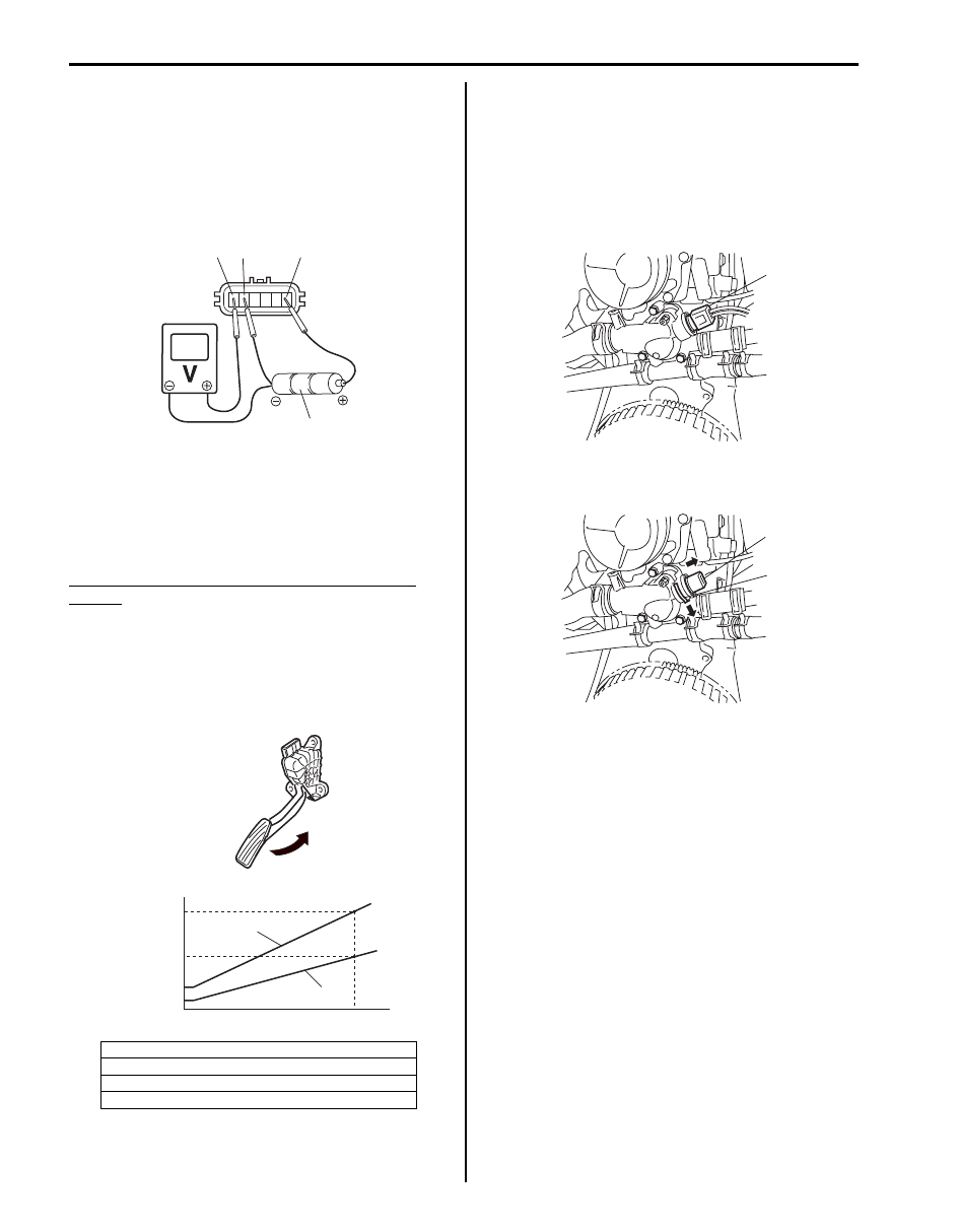
2) For accelerator pedal position (APP) sensor (sub), 

arrange 3 new 1.5 V batteries (1) in series (check 
that total voltage is 4.7 – 5.0 V) and connect its 
positive terminal to “Vin 2” terminal (2) and negative 
terminal to “Ground 2” terminal (3) of sensor. Then 
using voltmeter connect positive terminal to “Volt 2” 
terminal (4) of sensor and negative terminal to 
battery.

3) Measure output voltage variation while accelerator 

pedal is no depressed and fully depressed as 
following specification.

If sensor voltage is out of specified value or does not 
vary linearly as the following graph, replace accelerator 
pedal position assembly.

Accelerator pedal position (APP) sensor output 
voltage
Accelerator pedal position (APP) sensor (main) 
output voltage [A]: 0.82 – 3.50 V, varying according 
to depressed extent of accelerator pedal
Accelerator pedal position (APP) sensor (Sub) 
output voltage [B]: 0.44 – 1.74 V, varying according 
to depressed extent of accelerator pedal

Engine Coolant Temperature (ECT) Sensor 
Removal and Installation

S6JB0A1326011

Removal

1) Disconnect negative cable at battery.
2) Drain cooling system referring to “Cooling System 

Description: For Diesel Engine Model in Section 1F”.

3) Disconnect ECT sensor connector (1).

4) Remove ECT sensor (1) from thermostat assembly 

by removing clip (2).

Installation
Reverse removal procedure for installation noting the 
following.
• Check ECT sensor O-ring for damage.

If malfunction is found, replace ECT sensor.

• Refill cooling system referring to “Cooling System 

Refilling: For Diesel Engine Model in Section 1F”.

• Check cooling system leakage referring to “Engine 

Cooling System Inspection and Cleaning: For Diesel 
Engine Model in Section 1F”
.

[C]: Sensor output voltage
[D]: Idle position of accelerator pedal 

[E]: Fully depressed position of accelerator pedal

[F]: Pedal stroke

1

2

3

4

I5JB0A130020-02

[C]

[B]

[D]

[F]

[E]

[A]

1.74 - 2.17 V

0.65 - 0.82 V

3.50 - 4.27 V

0.30 - 0.44 V

I5JB0A130021-05

1

I5JB0B130003-01

1

2

I5JB0B130004-01

Engine Electrical Devices: For Diesel Engine Model 1C-29

Engine Coolant Temperature (ECT) Sensor 
Inspection

S6JB0A1326012

1) Remove ECT sensor referring to “Engine Coolant 

Temperature (ECT) Sensor Removal and 
Installation: For Diesel Engine Model”.

2) Immerse temperature sensing part of ECT sensor in 

water and measure resistance between sensor 
terminal (1) and (2) while heating water gradually.
If measured resistance doesn’t show such 
characteristic as shown, replace ECT sensor.

ECT sensor resistance

Camshaft Position (CMP) Sensor Removal and 
Installation

S6JB0A1326013

Removal

1) Disconnect negative cable at battery.
2) Remove injector cover referring to “Cylinder Head 

Cover Removal and Installation: For F9Q Engine in 
Section 1D”
.

3) Remove CMP sensor (1) from generator upper 

bracket support.

Installation
Reverse removal procedure for installation noting the 
following.
• Clean CMP sensor and protrusion of camshaft pulley 

before installation.

• Tighten throttle body to EGR valve pipe to specified 

torque.

Tightening torque
Throttle body to EGR valve pipe:  21 N·m (2.1 kgf-
m, 15.5 lb-ft)

Crankshaft Position (CKP) Sensor (Engine 
Speed Sensor) Removal and Installation

S6JB0A1326014

Removal

1) Disconnect negative cable at battery.
2) Hoist vehicle.
3) Disconnect connector (1) from CKP sensor (2).
4) Remove CKP sensor from transmission case.

Water temperature 

°C (°F)

Resistance (k

)

25 (77)

2.140 – 2.364

50 (122)

0.770 – 0.850

80 (176)

0.272 – 0.288

[A]: Resistance
[B]: Temperature

I4SN0A132012-01

1

I5JB0B130005-01

1

2

I5JB0B130007-01

1C-30 Engine Electrical Devices: For Diesel Engine Model

Installation
Reverse removal procedure for installation noting the 
following.
• Clean CKP sensor and sensor rotor teeth before 

installation.

• Tighten CKP sensor bolt to specified torque.

Tightening torque
CKP sensor bolt (a):  11 N·m (1.1 kgf-m, 8.0 lb-ft)

Crankshaft Position (CKP) (Engine Speed 
Sensor) Sensor Inspection

S6JB0A1326015

1) Remove CKP sensor referring to “Crankshaft 

Position (CKP) Sensor (Engine Speed Sensor) 
Removal and Installation: For Diesel Engine Model”.

2) Check that CKP sensor (1) and sensor rotor tooth (2) 

are free from any metal particles and damage.

3) Check that resistance between terminals of CKP 

sensor is within specification.
If resistance is not as specified, replace CKP sensor.

CKP sensor resistance
612 – 880 

 at 20 °C, 68 °F

Boost Pressure Sensor Removal and 
Installation

S6JB0A1326020

Removal

1) Disconnect negative cable at battery.
2) Disconnect connector (1) from boost pressure 

sensor (2).

3) Remove boost pressure sensor from throttle body to 

EGR valve pipe.

Installation
Reverse removal procedure for installation noting the 
following.
• Check boost pressure sensor O-ring for damage.

If malfunction is found, replace boost pressure sensor.

• Tighten boost pressure sensor bolt to specified 

torque.

Tightening torque
Boost pressure sensor bolt (a):  8 N·m (0.8 kgf-m, 
6.0 lb-ft)

(a)

I5JB0B130008-01

I5JB0B130009-02

I5JB0B130010-01

2

1

I5JB0B130011-01

(a)

I6JB0A132002-01

Engine Electrical Devices: For Diesel Engine Model 1C-31

Main Relay and Fuel Heater Relay Inspection

S6JB0A1326022

1) Disconnect negative cable at battery.
2) Remove main relay (1) and fuel heater relay (2) from 

relay connector.

3) Check that there is no continuity between terminal 

“c” and “d”.
If there is continuity, replace relay.

4) Connect battery positive (+) terminal to terminal “b” 

of relay. Connect battery negative (–) terminal “a” of 
relay.
Check continuity between terminal “c” and “d”.
If there is no continuity when relay is connected to 
the battery, replace relay.

Glow Plug Control Module Removal and 
Installation

S6JB0A1326023

Removal

1) Disconnect negative cable at battery.
2) Disconnect glow plug control module unit connector 

(1).

3) Remove glow plug control module unit (2) from 

bracket.

Installation
Reverse removal procedure for installation.

Boost Pressure Control Solenoid Valve 
Removal and Installation

S6JB0A1326029

Removal

1) Disconnect negative cable at battery.
2) Detach boost pressure control solenoid valve (1).
3) Disconnect boost pressure control solenoid valve 

connector (2) and hoses (3) from boost pressure 
control solenoid valve.

Installation
Reverse removal procedure for installation.

1

2

I5JB0B130012-01

I4SN0A132024-01

2

1

I5JB0B130013-01

1

3

2

I5JB0B130014-02


Content   ..  115  116  117  118   ..