Suzuki Grand Vitara JB416 / JB420 / JB419. Manual - part 116
 

  Index      Suzuki     Suzuki Grand Vitara JB416 / JB420 / JB419 - service repair manual 2007 year


Search            


Content   ..  114  115  116  117   ..


Suzuki Grand Vitara JB416 / JB420 / JB419. Manual - part 116


1C-24 Engine Electrical Devices: For Diesel Engine Model

Inlet Throttle Valve Data Initialization

S6JB0A1326026

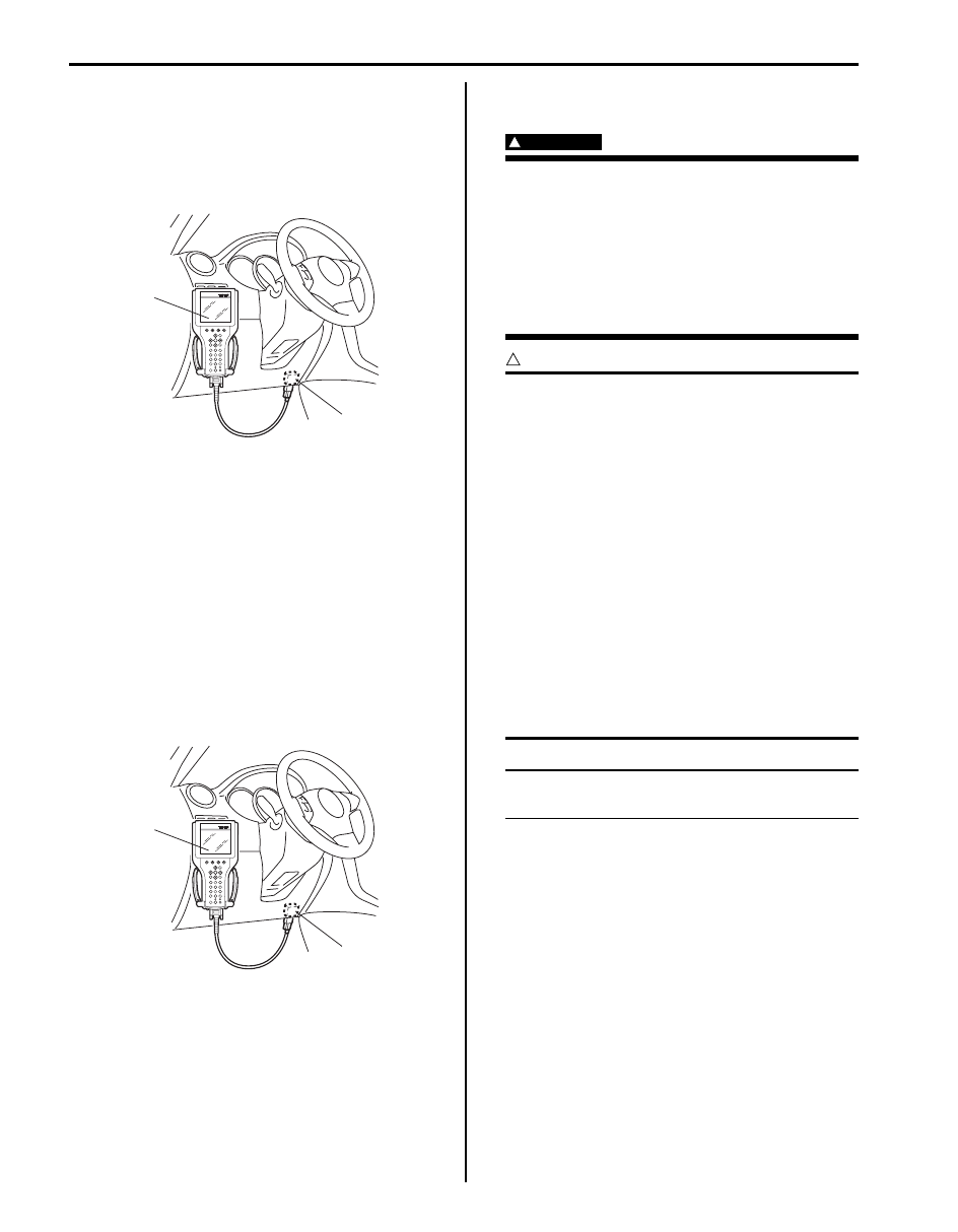
1) Connect SUZUKI scan tool to data link connector 

(DLC) (1) with ignition switch OFF.

Special tool
(A):  SUZUKI scan tool 

2) Turn ignition switch ON position and select “ECM 

setting” under “Miscellaneous test” (“MISC TEST”) 
mode of SUZUKI scan tool.

3) Perform “Initialize Inlet throttle valve data” on scan 

tool.

4) Turn ignition switch to OFF position and wait 40 

seconds or more.

Diesel Particulate Filter Data Initialization

S6JB0A1326027

1) Connect SUZUKI scan tool to data link connector 

(DLC) (1) with ignition switch OFF.

Special tool
(A):  SUZUKI scan tool 

2) Turn ignition switch ON position and select “ECM 

setting” under “Miscellaneous test” (“MISC TEST”) 
mode of SUZUKI scan tool.

3) Perform “Initialize Diesel PF data” on scan tool.
4) Turn ignition switch to OFF position and wait 40 

seconds or more.

Diesel Particulate Filter After-sales 
Regeneration Procedure

S6JB0A1326028

WARNING

!


During after-sales regeneration, exhaust gas 
temperature rises significantly and excessive 
smoke and strong smell occur.
In order to reduce risk of fire and personal 
injury, this work must be performed in 
outside of work shop or a well ventilated area 
with an exhaust gas extractor approved at 
400 

°C (750 °F) and nothing should be left in 

vicinity of exhaust system components.


CAUTION

!


• Check the engine oil level before 

performing this procedure to prevent the 
engine damage. Engine oil level should be 
between the Low and Full level marks on 
the gauge.

• It is essential to change engine oil after 

this procedure in order to avoid any 
damage to the engine.

• Only perform diesel particulate filter after-

sales regeneration under the following 
conditions.
– “DTC P1431: Clogged Diesel Particulate 

Filter Failures: For Diesel Engine Model 
in Section 1A”
 is detected.

– “DTC P1436: Diesel Particulate Filter 

Regeneration Request Failures: For 
Diesel Engine Model in Section 1A” 
is 
detected.


NOTE
For further detail of SUZUKI scan tool, refer 
to its operator’s manual.


1) Check engine oil level referring to “Engine Oil and 

Filter Change (Petrol Engine Model) in Section 0B”.

2) Locate vehicle in outside of workshop or well 

ventilated area with connecting exhaust gas 
extractor to exhaust pipe.

3) Connect SUZUKI scan tool to data link connector 

(DLC) with ignition switch OFF.

4) Start engine.
5) Select “Regeneration” under “Miscellaneous test” 

(“MISC. TEST”) of SUZUKI scan tool, and follow 
instructions displayed in SUZUKI scan tool.

(A)

1

I5JB0A110019-01

(A)

1

I5JB0A110019-01

Engine Electrical Devices: For Diesel Engine Model 1C-25

6) Proceed after-sales regeneration automatically as 

follows.

NOTE
Ensure to perform each step of regeneration 
by observing carefully the engine speed and 
the engine sound at each step. Because this 
procedure does not finish automatically and 
SUZUKI scan tool does not indicate any 
status of this procedure and the result of 
regeneration.


a) Phase 1: Warming up

The engine speed is raised to 1500 rpm for at 
least 3 minutes or until engine coolant 
temperature reaches 80 

°C (176 °F)

b) Phase 2: Regenerating

Injection timing is shifted to post injection (a 
change in the engine operation sound can be 
heard) and start regeneration.

NOTE
Phase 2 lasts approximately 20 minutes.


c) Phase 3: Cooling down

The injection is shifted to normal timing again.

CAUTION

!


To avoid thermal shock in the diesel 
particulate filter, do not stop engine at this 
step.


7) Confirm “Diesel PF inlet Temp” under “Data list” of 

SUZUKI scan tool, and wait until it decreases to 200 

°C (392 °F) or less.

8) Stop engine.
9) Turn ignition switch to OFF position, and wait for 15 

minutes or more.

10) Clear DTC referring to “DTC Clearance: For Diesel 

Engine Model in Section 1A”.

11) After engine is cooled, replace engine oil and oil filter 

referring to “Engine Oil and Filter Change (Petrol 
Engine Model) in Section 0B”.

12) Check as follows that aftersales-regeneration is 

correctly performed.

CAUTION

!


When driving, be sure to select in safe place 
where there is neither any traffic nor any 
traffic accident possibility and be very 
careful during driving to avoid occurrence of 
an accident.


a) Drive vehicle in the following each condition in 

order to make ECU recognize actually soot mass 
after after-sales regeneration.
i)

At 80 km/h for 10 minutes

ii) At 40 km/h for 5 minutes

b) Using SUZUKI scan tool, check that “Diesel PF 

soot mass” parameter is 8 g (0.28 oz) or less.
If it is over 8g (0.28 oz), aftersales regeneration 
is not correctly performed. Proceed to next step.

13) If aftersales regeneration is not correctly performed, 

check as follows.

CAUTION

!


Be sure to change engine oil after each 
aftersales regeneration.
Otherwise, engine will be damaged due to 
degraded engine oil.


a) Check that connection and/or hose of differential 

pressure sensor.
If faulty condition is found, repair or replace it.

b) Restart aftersales-regeneration referring to 

“Diesel Particulate Filter After-sales 
Regeneration Procedure: For Diesel Engine 
Model” an
d check the following condition during 
this after-sales regeneration.
• Check exhaust system for leakage.

If leakage is found, repair or replace faulty 
condition.

• Using SUZUKI scan tool, check that the 

following parameters are over 550 

°C 

(1022

°F).

If not, replace catalytic converter referring to 
“Exhaust System Components: For Diesel 
Engine Model in Section 1K”.
– Diesel PF in Temp
– Diesel PF out Temp

c) After after-sales regeneration, check “Diesel PF 

soot mass” in the same manner as step 12).
If “Diesel PF soot mass” is over 8 g (0.28 oz) 
again, replace diesel particulate filter referring to 
“Diesel Particulate Filter Removal and 
Installation: For Diesel Engine Model in Section 
1K”.

1C-26 Engine Electrical Devices: For Diesel Engine Model

Glow Plug Removal and Installation

S6JB0A1326007

Removal

CAUTION

!


• Do not damage heating section of the glow 

plug.

• Do not use glow plug that has been 

dropped.

• When removing glow plug, first loosen it 

with a tool so that one or more screw 
threads remain engaged, then loosen and 
remove by hand.


1) Disconnect negative (–) cable at battery.
2) Remove injector cover referring to “Cylinder Head 

Cover Removal and Installation: For F9Q Engine in 
Section 1D”.

3) Pull off glow plug wires (1).
4) Clean outside of glow plug to avoid any dirt entering 

cylinder head.

5) Remove glow plugs (2) from cylinder head.

Installation
For installation, reverse removal procedure noting the 
following.
• Tightening glow plug (1) to specified torque.

Tightening torque
Glow plug (a):  15 N·m (1.5 kgf-m, 11.0 lb-ft)

• Connect glow plug wires (2) securely.

Glow Plug Inspection

S6JB0A1326008

1) Disconnect negative (–) cable at battery.
2) Remove injector cover referring to “Cylinder Head 

Cover Removal and Installation: For F9Q Engine in 
Section 1D”.

3) Disconnect glow plug wires.
4) Check resistance between glow plug and engine 

ground.
If resistance is out of specification, replace glow 
plug.

Glow plug resistance
Approx. 0.6 

Accelerator Pedal Position (APP) Sensor 
Assembly On-Vehicle Inspection

S6JB0A1326037

1) Check that accelerator pedal position (APP) sensor 

assembly has been mounted to vehicle body 
properly (no pinched floor carpet, etc.).
If mounting is not properly, reinstall accelerator pedal 
position (APP) sensor assembly properly referring to 
“Accelerator Pedal Position (APP) Sensor Assembly 
Removal and Installation: For Diesel Engine Model”.

2) Connect SUZUKI scan tool to DLC with ignition 

switch turned OFF.

Special tool
:  SUZUKI scan tool 

3) Turn ON ignition switch and select “Date List” mode 

on scan tool.

1

1

2

I5JB0B130021-01

2

2

1, (a)

I5JB0B130022-01

I4SN0A132006-01

Engine Electrical Devices: For Diesel Engine Model 1C-27

4) Check that accelerator pedal position sensor voltage 

varies as the following graph.
If sensor voltage is out of specified value or does not 
vary linearly as the following graph, check 
accelerator to “Accelerator Pedal Position (APP) 
Sensor Assembly Inspection: For Diesel Engine 
Model”.

Accelerator Pedal Position (APP) Sensor 
Assembly Removal and Installation

S6JB0A1326038

CAUTION

!


• Do not expose accelerator pedal position 

(APP) sensor assembly to excessive shock 
like a dropping it. If accelerator pedal 
position (APP) sensor assembly has been 
exposed to excessive shock, it should be 
replaced.

• Be careful not to expose sensor section of 

accelerator pedal position (APP) sensor 
assembly to water.


Removal 

1) Disconnect negative cable at battery.
2) Disconnect connector from accelerator pedal 

position (APP) sensor assembly.

3) Remove accelerator pedal position (APP) sensor 

assembly from its bracket.

Installation
Reverse removal procedure for installation noting the 
following.
• Tighten accelerator pedal position (APP) sensor 

assembly upper nut (1) first and then lower nuts (2) to 
specified torque.

Tightening torque
Accelerator pedal position (APP) sensor assembly 
nut  (a):  6.0 N·m (0.6 kgf-m, 4.5 lb-ft)

• If APP sensor assembly bracket is removed, tighten 

its mounting nuts to specified torque.

Tightening torque
APP sensor assembly bracket nut:  6.0 N·m (0.6 
kgf-m, 4.3 lb-ft)

• Connect connector to accelerator pedal position 

(APP) sensor assembly securely.

Accelerator Pedal Position (APP) Sensor 
Assembly Inspection

S6JB0A1326039

Check accelerator pedal position (APP) sensor (main 
and sub) output voltage as following steps.

1) For accelerator pedal position (APP) sensor (main), 

arrange 3 new 1.5 V batteries (1) in series (check 
that total voltage is 4.7 – 5.0 V) and connect its 
positive terminal to “Vin 1” terminal (2) and negative 
terminal to “Ground 1” terminal (3) of sensor. Then 
using voltmeter, connect positive terminal to “Volt 1” 
terminal (4) of sensor and negative terminal to 
battery.

[A]: Accelerator pedal position (APP) sensor (main) voltage
[B]: Accelerator pedal position (APP) sensor (sub) voltage

[C]: Sensor output voltage 
[D]: Idle position of accelerator pedal 

[E]: Full depressed position of accelerator pedal 

[F]: Pedal stroke

[C]

[B]

[D]

[F]

[E]

[A]

1.74 - 2.17 V

0.65 - 0.82 V

3.50 - 4.27 V

0.30 - 0.44 V

I5JB0A130018-05

1, (a)

2, (a)

I5JB0A130036-01

1

2

3

4

I5JB0A130019-02


Content   ..  114  115  116  117   ..