Suzuki Grand Vitara JB416 / JB420 / JB419. Manual - part 23
 

  Index      Suzuki     Suzuki Grand Vitara JB416 / JB420 / JB419 - service repair manual 2007 year


Search            


Content   ..  21  22  23  24   ..


Suzuki Grand Vitara JB416 / JB420 / JB419. Manual - part 23


1A-39 Engine General Information and Diagnosis: For Petrol Engine Model

For Vehicle Equipped with A/T
When using OBD generic scan tool, not only the previous star (*) marked ECM DTC(s) but also the following DTC(s) is 
displayed on OBD generic scan tool simultaneously.

Fail-Safe Table

S6JB0A1114006

When any of the following DTCs is detected, ECM enters fail-safe mode as long as malfunction continues to exist but 
that mode is canceled when ECM detects normal condition after that.

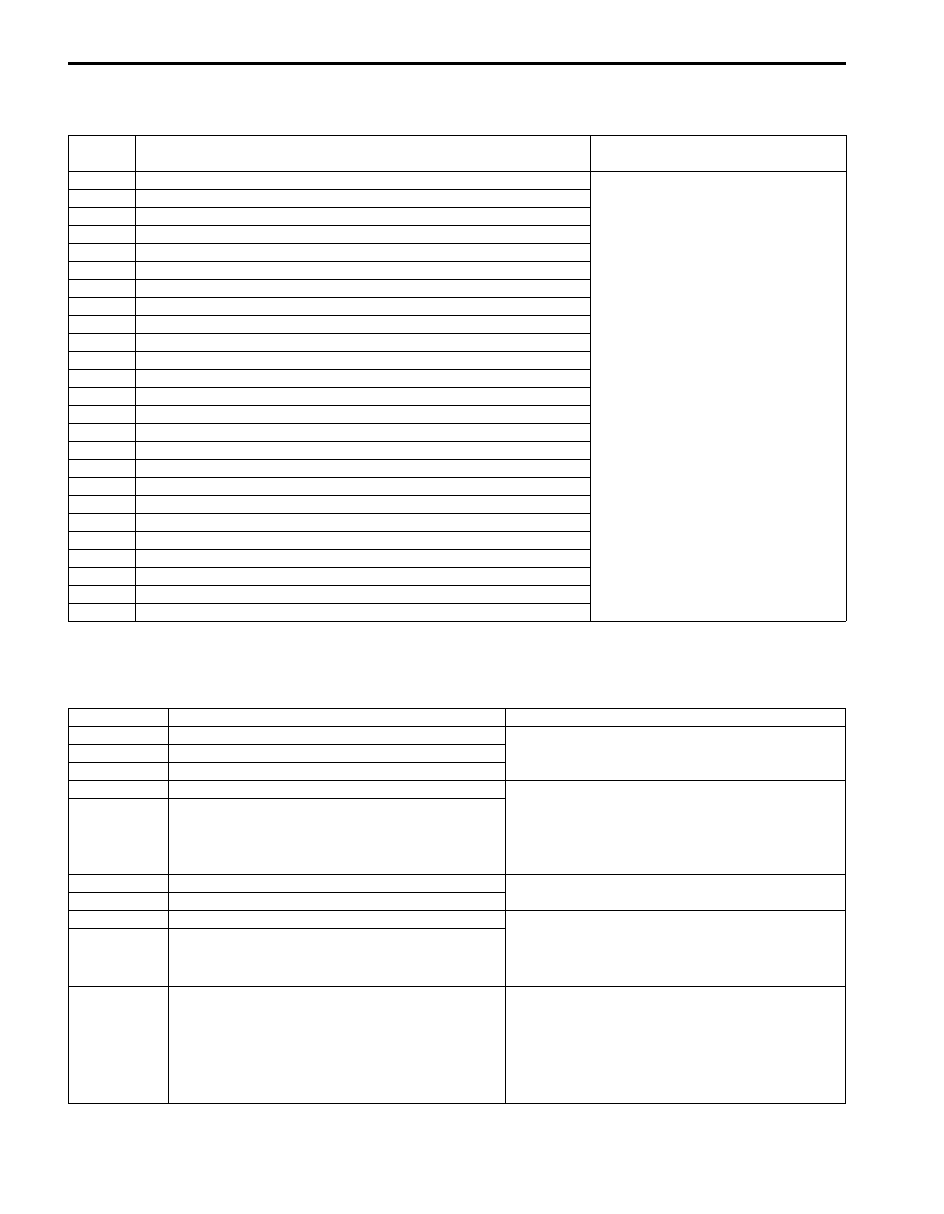
DTC No.

Detecting item

Detecting condition

(DTC will set when detecting)

*P0705 Transmission range sensor circuit malfunction (PRNDL input)

Refer to “DTC Table in Section 5A”.

*P0707 Transmission range sensor circuit low
*P0712 Transmission fluid temperature sensor circuit low
*P0713 Transmission fluid temperature sensor circuit high
*P0717 Input / Turbine speed sensor circuit no signal
*P0722 Output speed sensor circuit no signal
*P0741 Torque converter clutch circuit performance or stuck off
*P0742 Torque converter clutch circuit stuck on
*P0751 Shift solenoid-A (No.1) performance or stuck off
*P0752 Shift solenoid-A (No.1) stuck on
*P0756 Shift solenoid-B (No.2) performance or stuck off
*P0757 Shift solenoid-B (No.2) stuck on
*P0962 Pressure control solenoid control circuit low
*P0963 Pressure control solenoid control circuit high
*P0973 Shift solenoid-A (No.1) control circuit low
*P0974 Shift solenoid-A (No.1) control circuit high
*P0976 Shift solenoid-B (No.2) control circuit low
*P0977 Shift solenoid-B (No.2) control circuit high
*P1702 Internal control module memory check sum error
*P1774 Control module communication bus off
*P1777 TCM lost communication with ECM (Reception error)
*P1874 4L switch circuit malfunction (Short)
*P1875 4L switch circuit malfunction (Open)
*P2763 Torque converter clutch pressure control solenoid control circuit high
*P2764 Torque converter clutch pressure control solenoid control circuit low

DTC No.

Detected item

Fail-safe operation

)

 P0030

HO2S heater control circuit (Sensor-1)

ECM stops air/fuel ratio control.

)

 P0031

HO2S heater control circuit low (Sensor-1)

)

 P0032

HO2S heater control circuit high (Sensor-1)

)

 P0102

Mass air flow circuit low input

• ECM controls injector drive time (fuel injection 

volume) according to throttle valve opening 
(closed throttle position or not).

• ECM stops EGR control.

)

 P0103

Mass air flow circuit high input

)

 P0112

Intake air temperature sensor circuit low

ECM controls actuators assuming that intake air 
temperature is 20 

°C (68 °F).

)

 P0113

Intake air temperature sensor circuit high

)

 P0117

Engine coolant temperature circuit low

• ECM controls actuators assuming that engine 

coolant temperature is 80 

°C (176 °F).

• ECM operates radiator cooling fan.

)

 P0118

Engine coolant temperature circuit high

)

 P0122

Throttle position sensor (main) circuit low

• ECM turns off throttle actuator control relay and 

throttle valve is fixed at the opening of about 7° 
from its completely closed position (default 
opening).

• ECM controls fuel cut at specified engine speed.
• ECM stops air/fuel ratio control.

Engine General Information and Diagnosis: For Petrol Engine Model 1A-40

)

 P0123

Throttle position sensor (main) circuit high

• ECM turns off throttle actuator control relay and 

throttle valve is fixed at the opening of about 7° 
from its completely closed position (default 
opening).

• ECM controls fuel cut at specified engine speed.
• ECM stops air/fuel ratio control.

)

 P0131

O2 sensor (HO2S) circuit low voltage (Sensor-1)

ECM stops air/fuel ratio control.

)

 P0132

O2 sensor (HO2S) circuit high voltage (Sensor-1)

)

 P0134

O2 sensor (HO2S) circuit no activity detected 
(Sensor-1)

)

 P0222

Throttle position sensor (sub) circuit low

• ECM turns off throttle actuator control relay and 

throttle valve is fixed at the opening of about 7° 
from its completely closed position (default 
opening).

• ECM controls fuel cut at specified engine speed.

)

 P0223

Throttle position sensor (sub) circuit high

)

 P0335

Crankshaft position sensor circuit

Ignition timing is fixed.

)

 P0500

Vehicle speed sensor

ECM controls actuators assuming that vehicle 
speed is 0 km/h (0 mile/h).

)

 P2101

Throttle actuator control motor circuit range / 
performance

• ECM turns off throttle actuator control relay and 

throttle valve is fixed at the opening of about 7

° 

from its completely closed position (default 
opening).

• ECM controls fuel cut at specified engine speed.

)

 P2102

Throttle actuator control motor circuit low

)

 P2103

Throttle actuator control motor circuit high

ECM controls fuel cut at specified engine speed.

)

 P2111

Throttle actuator control system – stuck open

• Throttle valve is fixed at the opening of about 7

° 

from its completely closed position (default 
opening).

• ECM controls fuel cut at specified engine speed.

)

 P2119

Throttle actuator control throttle body range / 
performance

• ECM turns off throttle actuator control relay and 

throttle valve is fixed at the opening of about 7

° 

from its completely closed position (default 
opening).

• ECM controls fuel cut at specified engine speed.

)

 P2122

Pedal position sensor (main) circuit low input

• Throttle valve is fixed at the opening of about 7

° 

from its completely closed position (default 
opening).

• ECM controls fuel cut at specified engine speed.

)

 P2123

Pedal position sensor (main) circuit high input

)

 P2127

Pedal position sensor (sub) circuit low input

)

 P2128

Pedal position sensor (sub) circuit high input

)

 P2135

Throttle position sensor (main) / (sub) voltage 
correlation

• ECM turns off throttle actuator control relay and 

throttle valve is fixed at the opening of about 7

° 

from its completely closed position (default 
opening).

• ECM controls fuel cut at specified engine speed.

)

 P2138

Pedal position sensor (main) / (sub) voltage 
correlation

• Throttle valve is fixed at the opening of about 7

° 

from its completely closed position (default 
opening).

• ECM controls fuel cut at specified engine speed.

)

 P2227

Barometric pressure sensor performance problem

ECM controls actuators assuming that barometric 
pressure is 101.33 kPa (762 mmHg).

DTC No.

Detected item

Fail-safe operation

1A-41 Engine General Information and Diagnosis: For Petrol Engine Model

Scan Tool Data

S6JB0A1114007

As the data values are standard values estimated on the basis of values obtained from the normally operating vehicles 
by using a scan tool, use them as reference values. Even when the vehicle is in good condition, there may be cases 
where the checked value does not fall within each specified data range. Therefore, judgment as abnormal should not 
be made by checking with these data alone.
Also, conditions that can be checked by the scan tool are those detected by ECM and output from ECM as commands 
and there may be cases where the engine or actuator is not operating (in the condition) as indicated by the scan tool. 
Be sure to use the timing light to check the ignition timing.

NOTE

• With the generic scan tool, only star (*) marked data in the following table can be read.
• When checking the data with the engine running at idle or racing, be sure to shift M/T gear to the 

neutral gear position and A/T gear to the “Park” position and pull the parking brake fully. Also, if 
nothing or “no load” is indicated, turn OFF A/C (if equipped with A/C), all electric loads, P/S and all 
the other necessary switches.


Scan tool data

Vehicle condition

Normal condition / 

reference values

*

)

COOLANT TEMP 

(ENGINE COOLANT TEMP.)

At specified idle speed after warming up

80 – 100 

°C, 176 – 212 °F

)INTAKE AIR TEMP. 

At specified idle speed after warming up

–5 

°C (23 °F) + environmental 

temp. to 40 

°C (104 °F) + 

environmental temp.

)ENGINE SPEED 

It idling with no load after warming up

Desired idle speed 

± 50 rpm

)

DESIRED IDLE (DESIRED 

IDLE SPEED)

It idling with radiator cooling fan stopped and all 
electrical parts turned OFF after warming up, M/T at 
neutral

650 rpm (for J20 engine), 660 

rpm (for M16 engine)

*

)

MAF (MASS AIR FLOW 

RATE)

At specified idle speed with no load after warming 
up

1.0 – 4.0 g/s 0.14 – 0.52 lb/

min.

At 2500 r/min. with no load after warming up

4.0 – 12.0 g/s 0.53 – 1.58 lb/

min.

*

)

CALC LOAD 

(CALCULATED LOAD 
VALUE)

At specified idle speed with no load after warming 
up

0 – 10%

At 2500 r/min. with no load after warming up

0 – 10%

*

)

MAP (INTAKE MANIFOLD 

ABSOLUTE PRESSURE)

At specified idle speed with no load after warming 
up

24 – 38 kPa, 7.1 – 11.2 in.Hg

*

)

THROTTLE POSITION 

(ABSOLUTE THROTTLE 
POSITION)

Ignition switch ON / 
warmed up engine 
stopped

Accelerator pedal released

0 – 5%

Accelerator pedal depressed 
fully

90 – 100%

)

 BAROMETRIC PRES

Barometric pressure is 

displayed

)

 FUEL TANK LEVEL

Ignition switch ON

0 – 100%

)

 BATTERY VOLTAGE 

Ignition switch ON / engine at stop

10 – 14 V

)

 BATTERY CURRENT (for 

J20 engine)

At 2000 r/min. with no load after warming up

10.0 – 16.0 A

At 2000 r/min. with headlight ON and blower motor 
switch at HI position after warming up

35.0 – 45.0 A

)

 BRAKE SWITCH

Ignition switch ON

Brake pedal is released

OFF

Brake pedal is depressed

ON

)

 INTAKE TUNING SOL 

(INTAKE MANIFOLD 
TUNING VALVE) (for J20 
engine) 

At specified idle speed after warming up

ON

Engine speed at 4700 rpm or more

OFF

*

)

 FUEL SYSTEM B1 (FUEL 

SYSTEM STATUS)

At specified idle speed after warming up

CLSD (closed loop)

*

)

 O2S B1 S2 (HEATED 

OXYGEN SENSOR-2)

At 2000 r/min. for 3 min. or longer after warming up

0.1 – 0.95 V

*

)

 SHORT FT B1 (SHORT 

TERM FUEL TRIM)

At specified idle speed after warming up

–20 – +20%

Engine General Information and Diagnosis: For Petrol Engine Model 1A-42

*

)

 LONG FT B1 (LONG 

TERM FUEL TRIM)

At specified idle speed after warming up

–20 – +20%

)

 TOTAL FUEL TRIM B1

At specified idle speed after warming up

–35 – +35%

*

)

 A/F B1 S1 CURRENT (A/F 

SENSOR OUTPUT 
CURRENT)

At specified idle speed after warming up

–0.20 – 0.10 mA

)

 FUEL CUT 

Engine at fuel cut condition

ON

Engine at other than fuel cut condition

OFF

)

 O2S B1 S2 ACT (HEATED 

OXYGEN SENSOR-2)

At specified idle speed after warming up

ACTIVE

)

 A/F B1 S1 ACT (A/F 

SENSOR)

At specified idle speed after warming up

ACTIVE

)

 CANIST PRG DUTY 

(EVAP CANISTER PURGE 
FLOW DUTY)

At specified idle speed after warming up

0%

*

)

 IGNITION ADVANCE 

(IGNITION TIMING 
ADVANCE FOR NO.1 
CYLINDER)

At specified idle speed with no load after warming 
up

5 – 15

° BTDC (for J20 engine), 

7 – 17

° BTDC (for M16 

engine)

)

 EGR VALVE OPENING

At specified idle speed after warming up

0%

)

 VVT GAP (TARGET-

ACTUAL POSITION) (for 
M16 engine)

At specified idle speed after warming up

0 – 3

°

)

 GENERATOR CONT 

DUTY (GENERATOR 
CONTROL DUTY)

At specified idle speed with no load after warming 
up

100%

)

 GENERATOR FIELD 

DUTY (GENERATOR FIELD 
COIL DUTY)

At specified idle speed with no load after warming 
up

10.0 – 50.0%

)

 FUEL PUMP

Within 2 seconds after ignition switch ON or engine 
running

ON

Engine at stop with ignition switch ON

OFF

)

 STARTER SW (STARTER 

SWITCH)

Ignition switch is turned to ST (engine cranking) 
position

ON

)

 A/C PRESSURE (A/C 

REFRIGERANT ABSOLUTE 
PRESSURE)

Engine running

A/C ON (A/C is operating) at 
ambient temperature: 30 

°C 

(86 

°F) and humidity: 50%

1300 – 1480 kPa (for J20 

engine), 1150 – 1280 kPa (for 

M16 engine) For more details, 

refer to pressure of high 

pressure gage under “A/C 

System Performance 

Inspection in Section 7B”.

A/C OFF (A/C is not 
operating) at ambient 
temperature: 30 

°C (86 °F) 

and engine coolant 
temperature: 90 – 100 

°C 

(194 – 212 

°F)

600 – 1000 kPa After longer 

than 10 min from A/C switch 

turned off

)

 A/C SWITCH

Engine running after warming up, A/C not operating

OFF

Engine running after warming up, A/C operating

ON

)

 A/C COMP RELAY

Engine running

A/C switch and blower motor 
switch turned ON

ON

A/C switch and blower motor 
switch turned OFF

OFF

)

 BLOWER FAN

Ignition switch ON

Blower fan switch: 5th speed 
position or more

ON

Blower fan switch: under 4th 
speed position

OFF

Scan tool data

Vehicle condition

Normal condition / 

reference values


Content   ..  21  22  23  24   ..