Suzuki Grand Vitara JB627. Manual - part 184
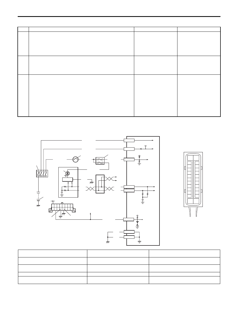
4E-17 ABS:
Troubleshooting
Serial Data Link Circuit Check
S6JB0B4504011
Step
Action
Yes
No
1
1) Make sure that:
• Parking brake is completely released.
• Brake fluid level is upper than the minimum level.
Are the check results OK?
Go to Step 2.
Release parking brake
completely and/or
replenish brake fluid.
2
1) Turn ignition switch to ON position.
Does “ABS” warning light come on steady?
Perform “ABS Warning
Light Comes ON
Steady” previously
outlined.
Go to Step 3.
3
1) CAN communication circuit between combination meter,
ABS (ESP
®) hydraulic unit / control module and BCM
referring to “DTC U1073: Control Module
Communication Bus Off”.
Is CAN communication circuit in good condition?
Substitute a known-
good combination meter
and recheck. If ABS
warning light remains
ON, substitute a known-
good ABS (ESP
®)
hydraulic unit / control
module assembly and
recheck.
Repair or replace.
3
4
2
1
12V
12V
E03-1
E03-14
E03-7
GRN/ORN
PPL/RED
BLK/YEL
WHT/GRN
WHT/RED
WHT/BLU
E03-13
E03-26
BLK
BLK
BLK
RED
WHT
RED
WHT
E03-12
E03-6
PPL/WHT
12V
+BB
E03-5
[A]
E03
10
11
9
8
G
G1
5
7
6
12
15
16
17
18
19
20
21
22
23
24
25
2
3
4
5
6
7
8
9
10
11
12
1
13
14
26
I5JB0A450012-02
[A]:
ABS (ESP
®) hydraulic unit / control module
connector (viewed from terminal side)
5. Combination meter
10. CAN junction
1. Battery
6. EBD warning light (Brake warning light)
11. To TCM, 4WD control module and keyless start
control module
2. Main fuse box
7. Light driver module
12. ABS (ESP
®) hydraulic unit / control module
assembly
3. Ignition switch
8. Data link connector (DLC)
4. Circuit fuse (in junction block assembly)
9. To ECM, TCM, BCM, SDM and 4WD
control module