Suzuki: Engine K6A-YH6. Manual - part 12


  Index      Suzuki     Suzuki: Engine K6A-YH6 - service repair manual 2008 year


Search            


Content   ..  10  11  12  13   ..


Suzuki: Engine K6A-YH6. Manual - part 12


DIAGNOSTIC TROUBLESHOOTING

6-5

6

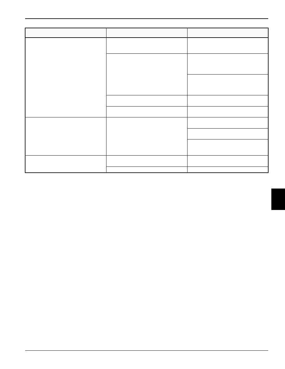
Excessive engine noise.

Valve train noise.

Check valve clearance. (See “Valve 

Clearance Check and Adjustment” on 
page 5-3.)

Crankshaft/connecting rod noise.

Check crankshaft, connecting rods, and 

bearings. (See “Lower Crankcase, 
Cylinder Block, and Crankshaft” on 
page 7-42.)

Check pistons, piston rings, piston pins, 

and small end of connecting rod. (See 
“Connecting Rods and Pistons” on 
page 7-38.)

Faulty timing chain or tension adjuster.

Check timing chain and tensioner. (See 

“Timing Chain” on page 7-14.)

Exhaust leak.

Check exhaust manifold. (See “Exhaust 

Manifold” on page 7-7.)

White exhaust smoke.

Coolant leaking into cylinder.

Check cylinder head. (See “Cylinder 

Head” on page 7-24.)

Check head gasket. (See “Cylinder Head” 

on page 7-24.)

Check cylinder liners. (See “Lower 

Crankcase, Cylinder Block, and 
Crankshaft” on page 7-42.)

Excessive engine vibration.

Loose or faulty crankshaft pulley.

Check crankshaft pulley. (See “Crankshaft 

Pulley” on page 7-37.)

Loose or faulty flywheel/flex plate.

Check flywheel/flex plate.

 Condition

Probable Cause

Remedy

REPAIR

7-3

7

7.1 Air Intake and Exhaust 
Systems

Throttle Position Sensor

Removal and Installation

See Figure 7-1.

Figure 7-1

1.

Remove screws (1) and throttle position sensor (2).

2.

Inspect throttle position sensor. Replace as needed.

Pressure Sensor

Removal and Installation

See Figure 7-2.

Figure 7-2

1.

Remove screws (2), pressure sensor (1), and O-ring 
(3).

2.

Inspect pressure sensor. Replace as needed.

Installation Notes

Always use new O-rings, gaskets, and seals.

Install pressure sensor by reversing the order of removal.

ISC (Idle Speed Control) Valve

Removal and Installation

See Figure 7-3.

Figure 7-3

1.

Remove screws (2), ISC valve (3), and O-ring (1).

2.

Inspect ISC valve. Replace as needed.

Installation Notes

Always use new O-rings, gaskets, and seals.

Install ISC valve by reversing the order of removal.

TN0713

1

2

TN0713

2

1

3

TN0691

2

3

1

7-4

REPAIR

7

PCV Valve

Removal and Installation

See Figure 7-4.

Figure 7-4

1.

Remove clamp (1) and hose (2).

2.

Remove PCV valve (4) from grommet (3).

3.

Inspect and test PCV valve. Replace as needed. 
(See “PCV Valve/Hose Test” on page 5-2.)

Installation Note

Install PCV valve by reversing the order of removal.

Throttle Body

Removal and Installation

See Figures 7-5 and 7-6.

Figure 7-5

1.

Remove cap screws (2) and throttle body (1).

Figure 7-6

2.

Remove throttle body gasket (3).

Installation Notes

Always use new O-rings, gaskets, and seals.

Install new gasket and throttle body by reversing the 
order of removal.

Intake Manifold

Removal

See Figure 7-7.

Figure 7-7

1.

Remove throttle body. (See “Throttle Body” on 
page 7-4.)

2.

Remove fuel rail and injectors. (See “Injectors” on 
page 7-9.)

3.

Remove knock sensor. (See “Knock Sensor” on 
page 7-37.)

4.

Remove PCV hose. (See “PCV Valve” on page 7-4.)

5.

Remove cap screw (4).

6.

Remove nine cap screws (2) and three nuts (3).

7.

Remove intake manifold (1).

TN0711

1

2

4

3

TN0737

1

2

TN0740

3

TN0736

4

1

3

3

2

2

2

REPAIR

7-5

7

Inspection

See Figure 7-8.

1.

Inspect intake manifold for cracks, damage, and 
distortion.

Figure 7-8

2.

Using a straightedge and a feeler gauge, inspect the 
mating face for distortion. Place the straightedge 
across bolt hole centers at the locations indicated. 
Measure any gaps with the feeler gauge. If the 
measurement exceeds the limit, replace intake 
manifold.

Intake Manifold Distortion Limit: 0.003 in. (0.07 mm)

Installation

See Figures 7-9 and 7-10.

Figure 7-9

NOTES

Clean intake manifold and cylinder head gasket surfaces 
before installation.

Always use new O-rings, gaskets, and seals.

1.

Install new intake manifold gasket (1).

Figure 7-10

2.

Install intake manifold (2) and cap screw (5).

3.

Install nine cap screws (3) and three nuts (4). Tighten 
to specification.

Intake Manifold Torque: 97 lb-in. (11 N•m)

4.

Install PCV hose. (See “PCV Valve” on page 7-4.)

5.

Install knock sensor. (See “Knock Sensor” on 
page 7-37.)

6.

Install fuel rail and injectors. (See “Injectors” on 
page 7-9.)

7.

Install throttle body. (See “Throttle Body” on 
page 7-4.)

TN0735

TN0735

1

TN0736

5

2

4

4

3

3

3


Content   ..  10  11  12  13   ..