Suzuki: Engine K6A-YH6. Manual - part 10
5-4
TESTS AND ADJUSTMENTS
5
IMPORTANT
The check and adjustment must be performed when
engine is cold.
Continue turning the crankshaft so that each
different cam lobe will point away from the shim face
successively. Measure each valve clearance at this
position. (All the valve clearances can be measured
during two complete turns of crankshaft.)
Valve clearance and adjustment may be done in pairs
(Example: #1 Intake valves, then #2 Intake valves,
and so on.)
The valve clearance measurement must be
performed with the timing chain installed in place.
Figure 5-8
3.
When the cam lobe (2) to be checked points 180°
away from the shim face, measure the clearance
between the camshaft and shim using a feeler gauge
(3).
4.
Check measurement against valve clearance
specification.
5.
Perform adjustment procedure if valve clearance is
out of specification.
Adjustment
Figure 5-9
1.
If the valve clearance is out of specification, adjust it
by replacing the shim (1).
2.
Ensure that the valve is closed for the shim being
adjusted and turn the tappet to bring its cutaway (2)
inward.
3.
Turn the crankshaft to open the valve needing
adjustment.
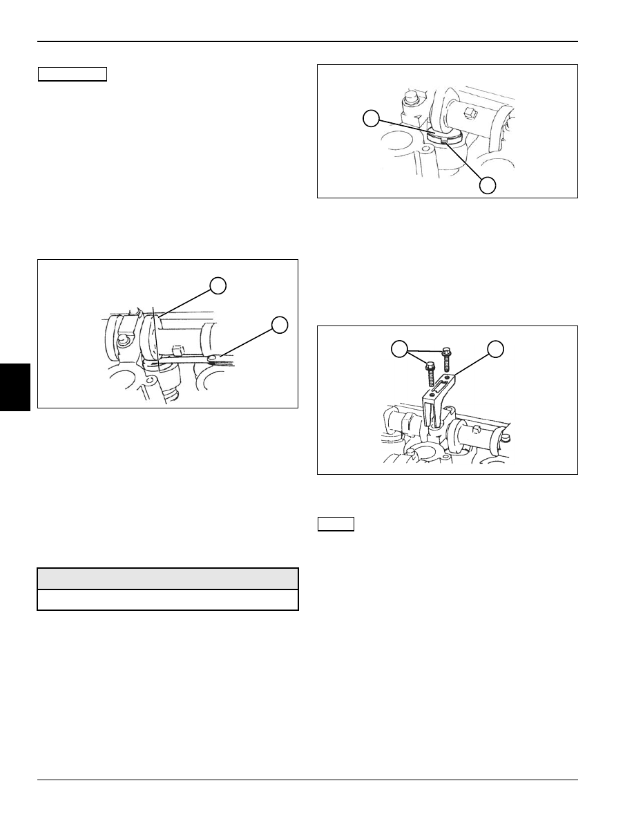
Figure 5-10
4.
Remove the camshaft housing cap screws (3).
NOTE
The special tool stamped with “IN” must be used for
intake camshaft and tool with “EX” for exhaust camshaft.
Check that the special tool is not pushing on the shim.
5.
Attach the special tool (4) with the camshaft housing
cap screws. Torque to specification.
Tightening Torque: 97 lb-in. (11 N•m)
Required Tools
Tappet Holder: Jacobsen PN 4139726
TN0360
180
°
2
3
TN0361
2
1
TN0362
3
4