Subaru XV Crosstrek (2016 year). Instruction - part 24
Cup holders
CAUTION
. Do not pick up a cup from the cup
holder or put a cup in the holder
while you are driving, as this may
distract you and lead to an
accident.
. Take care to avoid spills. Bev-
erages, if hot, might scald you
and/or your passengers. Spilled
beverages may also damage up-
holstery or carpets.
. When a cup in the rear passen-
ger
’s cup holder contains a bev-
erage, do not fold down the rear
seatback. Otherwise, the bever-
age could spill and, if the bev-
erage is hot, it could scald you
and/or your passengers.
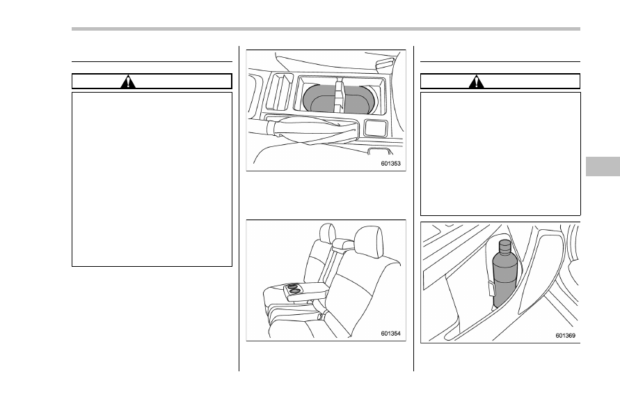
Front passenger
’s cup holder
A dual cup holder is built into the center
console.
Rear passenger
’s cup holder (if equipped)
A dual cup holder is built into the armrest.
Bottle holders
CAUTION
. Do not pick up a bottle from the
bottle holder or put a bottle in the
holder while you are driving, as
this may distract you and lead to
an accident.
. When placing a beverage in a
bottle holder, make sure it is
capped. Otherwise, the beverage
could spill when opening/closing
the door or while driving and, if
the beverage is hot, it could scald
you and/or your passengers.
The bottle holder equipped on each door
Interior equipment/Cup holders
– CONTINUED –
6-7