Subaru Impreza WRX (2014 year). Instruction - part 23
11-34
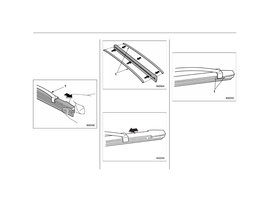
Maintenance and service/Replacement of wiper blades
&
Windshield wiper blade rub-
ber (type A and type B)
NOTE
The following illustrations show the
replacement procedures of the blade
rubber for a type A wiper blade assem-
bly, however the replacement proce-
dures are the same for a type B wiper
blade assembly.
1)
Metal support
1. Grasp the locked end of the blade
rubber assembly and pull it firmly until the
stoppers on the rubber are free of the
metal support.
1)
Metal spines
2. If the new blade rubber is not provided
with two metal spines, remove the metal
spines from the old blade rubber and
install them in the new blade rubber.
3. Align the claws of the metal support
with the grooves in the rubber and slide
the blade rubber assembly into the metal
support until it locks.
1)
Stopper
4. Be sure to position the claws at the
end of the metal support between the
stoppers on the rubber as shown. If the
rubber is not retained properly, the wiper
blade may scratch the windshield.
NOTE
The illustration shows the replacement
procedure for type A rubber wiper
blades, however the replacement pro-
cedure is the same for type B. Perform
the replacement of type B wiper blades
following the procedure in this section.