Subaru Legacy III (2000-2003 year). Manual - part 871


  Index      Subaru     Subaru Legacy III - service repair manual 2000-2003 year


Search            


Content   ..  869  870  871  872   ..


Subaru Legacy III (2000-2003 year). Manual - part 871


AC-20

HVAC SYSTEM (AUTO A/C) (DIAGNOSTICS)

DIAGNOSTICS FOR A/C SYSTEM FAILURE (LHD MODEL)

7. Diagnostics for A/C System Failure (LHD Model)

A: A/C AND/OR SELF-DIAGNOSIS SYSTEMS DO NOT OPERATE

TROUBLE SYMPTOM:
• “Set” temperature is not indicated on display, switch LEDs are faulty and switches do not operate.
• Self-diagnosis system does not operate.
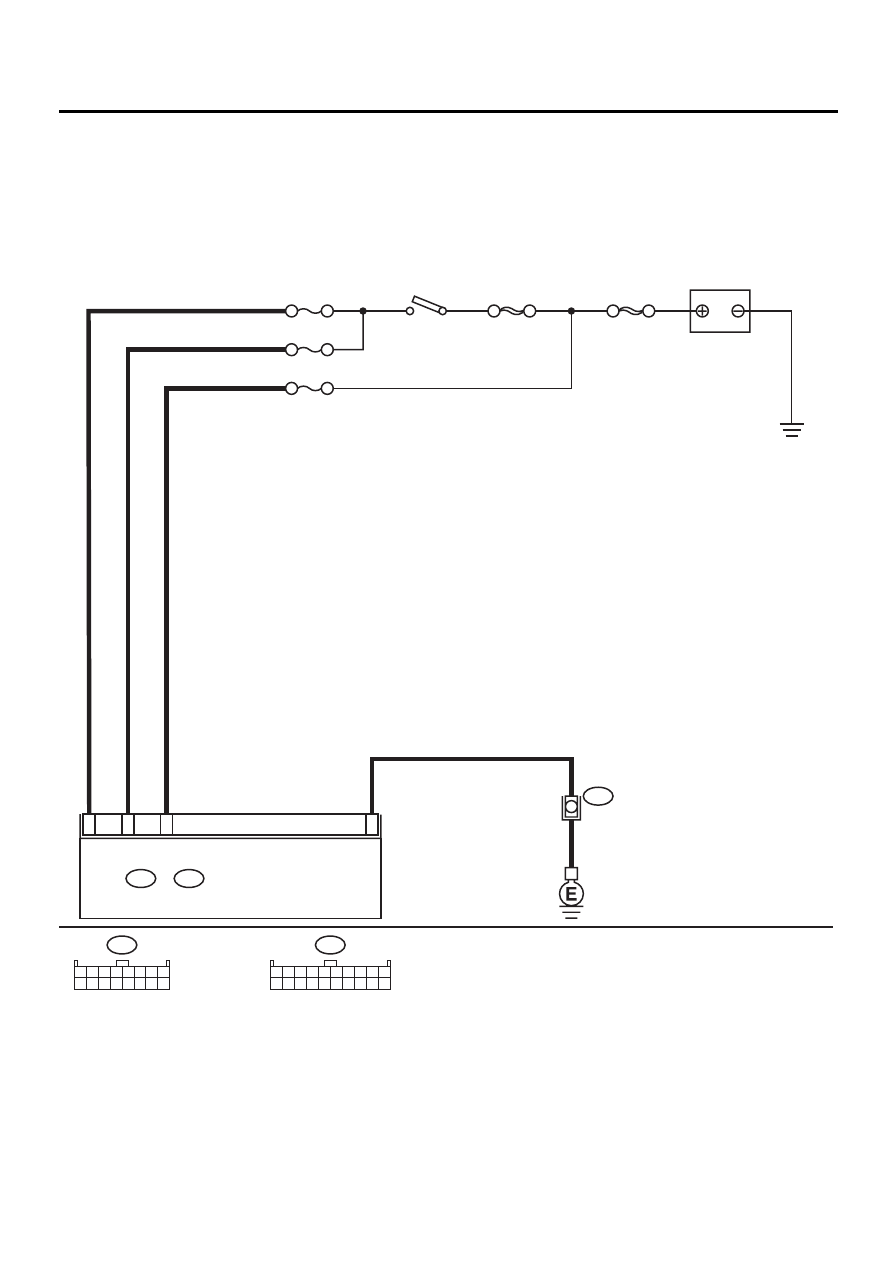
WIRING DIAGRAM:

AC-00318

A8

B2

B1

B12

i48

A:

i49

B:

AUTO A/C CONTROL MODULE

BATTERY

NO. 17

NO. 4

NO. 2

SBF-1

100A

SBF-4

i48

1 2 3 4 5 6 7 8
9 10 11 12 13 14 15 16

i49

1 2 3 4 5 6 7 8 9 10

11 12 13 14 15 16 17 18 19 20

A:

B:

IGNITION

SWITCH

i28

AC-21

HVAC SYSTEM (AUTO A/C) (DIAGNOSTICS)

DIAGNOSTICS FOR A/C SYSTEM FAILURE (LHD MODEL)

Step

Value

Yes

No

1

CHECK FUSE.
1) Turn ignition switch to OFF.
2) Remove fuse No. 2 from main fuse box.
3) Check condition of fuse.

Is the fuse blown-out?

Fuse is not blown-out.

Go to step 2.

Replace fuse.

2

CHECK FUSE.
1) Turn ignition switch to OFF.
2) Remove fuses No. 4 and No. 17 from fuse 

& relay box.

3) Check condition of fuse.

Is the fuse blown-out?

Fuse is not blown-out.

Go to step 3.

Replace fuse.

3

CHECK A/C CONTROL MODULE POWER 
CIRCUIT.
1) Disconnect A/C control module connector.
2) Measure voltage between A/C control mod-

ule connector terminal and chassis ground 
when turning ignition switch to OFF.

Connector & terminal

(i49) No. 1 (+) — Chassis ground (

−−−−

):

Does the measured value exceed the spec-
ified value?

10 V

Go to step 4.

Repair harness for 
power supply line.

4

CHECK A/C CONTROL MODULE POWER 
CIRCUIT.
Measure voltage between A/C control module 
connector terminal and chassis ground when 
turning ignition switch to ACC.

Connector & terminal

(i49) No. 2 (+) — Chassis ground (

−−−−

):

Does the measured value exceed the specified 
value?

10 V

Go to step 5.

Repair harness for 
power supply line.

5

CHECK A/C CONTROL MODULE POWER 
CIRCUIT.
Measure voltage between A/C control module 
connector terminal and chassis ground when 
turning ignition switch to ON.

Connector & terminal

(i48) No. 8 (+) — Chassis ground (

−−−−

):

Does the measured value exceed the specified 
value?

10 V

Go to step 6.

Repair harness for 
power supply line.

6

CHECK A/C CONTROL MODULE GROUND 
CIRCUIT.
Measure resistance of harness between A/C 
control module and chassis ground.

Connector & terminal

(i49) No. 12 — Chassis ground:

Is the measured value less than the specified 
value?

Go to step 7.

Repair harness for 
ground line.

7

CHECK POOR CONTACT.
Check poor contact in A/C control module con-
nector.
Is there poor contact in connector?

There is no poor contact.

Replace A/C con-
trol module.

Repair connector.

AC-22

HVAC SYSTEM (AUTO A/C) (DIAGNOSTICS)

DIAGNOSTICS FOR A/C SYSTEM FAILURE (LHD MODEL)

B: BLOWER MOTOR DOES NOT ROTATE

TROUBLE SYMPTOM:
• Blower motor does not rotate.
• Blower motor does not rotate in “HI”.
WIRING DIAGRAM:

AC-00319

A16

B11

B14

B50

B87

B86

B80

B36

i1

i20

BATTERY

NO. 1

NO. 2

NO. 17

SBF-3

SBF-1

SBF-4

i48

1 2 3 4 5 6 7 8
9 10 11 12 13 14 15 16

i49

1 2 3 4 5 6 7 8 9 10

11 12 13 14 15 16 17 18 19 20

A:

B:

2
1
4

2
1
3
4

1
2

BLOWER MOTOR
RESISTOR

BLOWER MOTOR

BLOWER MOTOR
RELAY

IGNITION

SWITCH

2

8

A6

B50

3 4

1 2

1 2 3 4
5 6 7 8

i20

B87

1
2

B86

3 4

1 2

B36

B4 B5 B6

A4 A5 A6

C5 C6

F6

D4 D5 D6

F1

H1

C4

G6

G1

C2

K1

M1 M2

K6

L1

D1 D2

A1 A2
B1 B2

I6

J6

L2

I1

J1

H6

M4 M5 M6

L4 L5 L6 

N5 N6

O4 O5 O6

N4

P4 P5

N2

O1 O2

P1 P2

N3

O3

P3

P6

A3

B3

C3

E4 E5 E6

E1 E2

i48

A:

i49

B:

AUTO A/C CONTROL MODULE

AC-23

HVAC SYSTEM (AUTO A/C) (DIAGNOSTICS)

DIAGNOSTICS FOR A/C SYSTEM FAILURE (LHD MODEL)

Step

Value

Yes

No

1

CHECK FUSE.
1) Remove No. 1, No. 2 and No. 17 fuses in 

fuse & relay box.

2) Check condition of fuses.

Are any of the fuses blown-out?

Fuse is not blown-out.

Go to step 2.

Replace fuse.

2

CHECK POWER SUPPLY TO BLOWER FAN 
MOTOR.
1) Turn ignition switch to ON.
2) Turn blower switch to ON.
3) Measure voltage between blower fan motor 

and chassis ground.

Connector & terminal

(B87) No. 1 (+) — Chassis ground (

−−−−

):

Does the measured value exceed the spec-
ified value?

10 V

Go to step 3.

Repair harness for 
blower fan motor 
power supply line.

3

CHECK BLOWER FAN MOTOR RELAY.
1) Turn ignition switch to OFF.
2) Remove blower fan motor relay.
3) Connect terminals as follows:

Positive terminal (+) of battery to terminal 
No. 1 of blower fan motor relay
Negative terminal (

) of battery to terminal 

No. 3 of blower fan motor relay

4) Measure resistance between No. 2 and No. 

4 terminals.

Terminals

No. 2 — No. 4:

Is the measured value less than the speci-
fied value?

Go to step 4.

Replace blower 
fan motor relay.

4

CHECK BLOWER FAN MOTOR.
1) Disconnect connector from blower fan 

motor.

2) Connect terminals as follows:

Positive terminal (+) of battery to terminal 
No. 1 of blower fan motor relay
Negative terminal (

) of battery to terminal 

No. 2 of blower fan motor relay

3) Make sure that blower fan motor is oper-

ated.
Does the blower fan motor operate?

Blower fan motor operates.

Go to step 5.

Replace blower 
fan motor.

5

CHECK POOR CONTACT.
Check poor contact in A/C control module con-
nector.
Is there poor contact in connector?

There no poor contact.

Replace A/C con-
trol module.

Repair connector.


Content   ..  869  870  871  872   ..