Subaru Legacy III (2000-2003 year). Manual - part 840
PS-48
POWER ASSISTED SYSTEM (POWER STEERING)
STEERING GEARBOX [LHD MODEL]
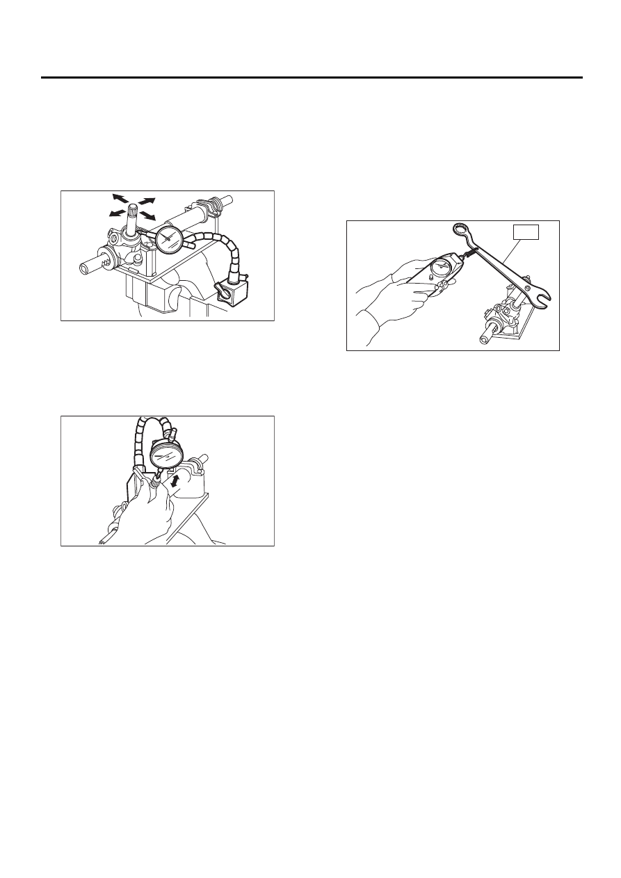
4. INPUT SHAFT PLAY
In radial direction:
Service limit
0.18 mm (0.0071 in) or less
On condition
P: 98 N (10 kgf, 22 lb)
In axial direction:
Service limit
0.5 mm (0.020 in) or less
On condition
P: 20 — 49 N (2 — 5 kgf, 4 — 11 lb)
5. TURNING RESISTANCE OF GEARBOX
Using ST, measure gearbox turning resistance.
ST
926230000
SPANNER
Service limit:
Straight-ahead position within 30 mm (1.18
in) from rack center
Less than 11.18 N (1.14 kgf, 2.51 lb)
Maximum allowable resistance
12.7 N (1.3 kgf, 2.9 lb)
PS-00103
P
PS-00104
P
PS-00105
ST