Subaru Legacy III (2000-2003 year). Manual - part 708


  Index      Subaru     Subaru Legacy III - service repair manual 2000-2003 year


Search            


Content   ..  706  707  708  709   ..


Subaru Legacy III (2000-2003 year). Manual - part 708


ABS-50

ABS (DIAGNOSTICS)

DIAGNOSTICS CHART WITH DIAGNOSIS CONNECTOR

L: DTC 29 ABNORMAL ABS SENSOR SIGNAL (ANY ONE OF FOUR)

DIAGNOSIS:
• Faulty ABS sensor signal (noise, irregular signal, etc.)
• Faulty tone wheel
• Turning wheels  freely for a long time
TROUBLE SYMPTOM:
• ABS does not operate.
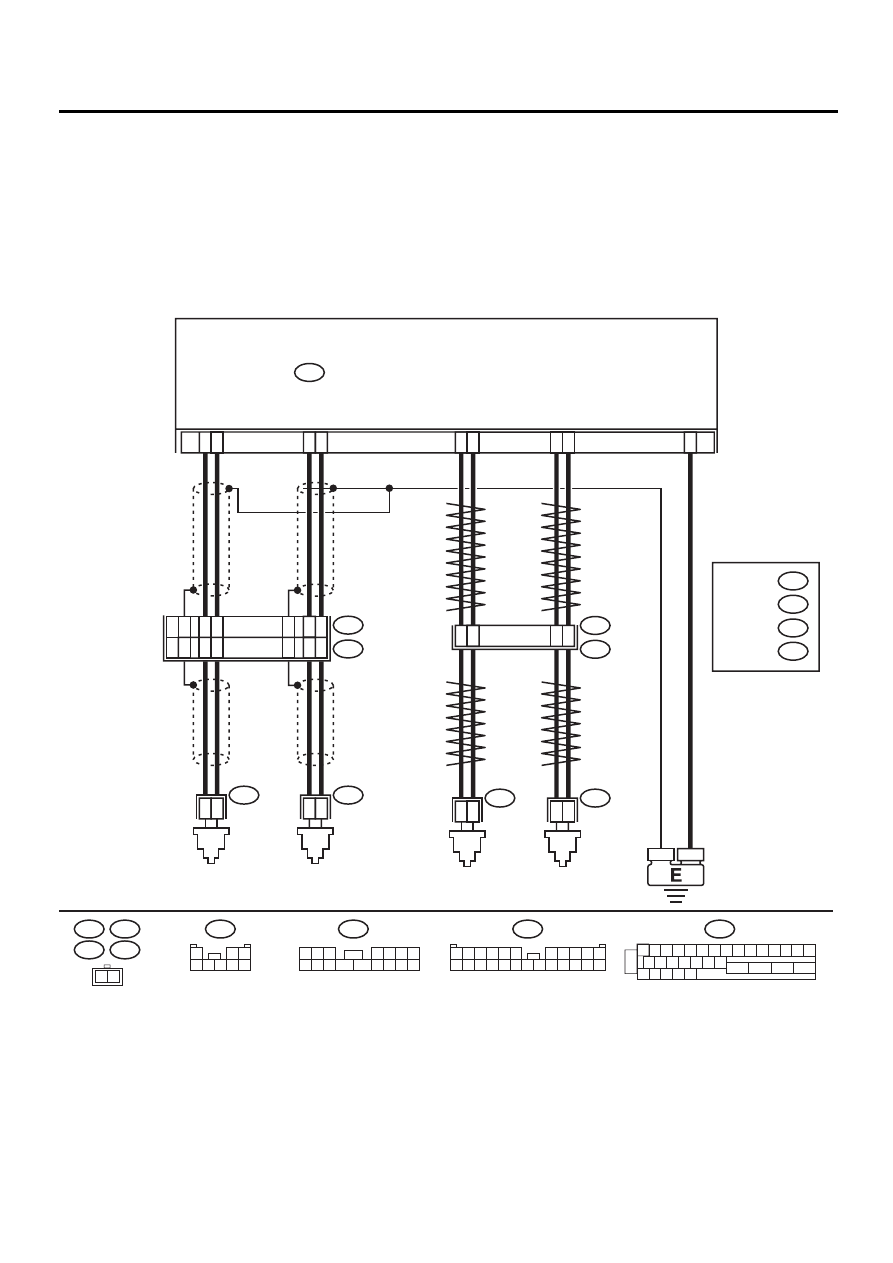
WIRING DIAGRAM:

ABS00309

R73

R72

F49

FRONT 

ABS

SENSOR LH

FRONT 

ABS

SENSOR RH

ABS CONTROL MODULE AND HYDRAULIC  CONTROL UNIT

F49

2

1

1 2 3 4 5 6 7 8 9 10 11 12 13 14 15

16 17 18 19 20 21 22

27 28 29 30 31

23

24

25

26

9

10

11

12

1

2

1

2

1

4

7

8

1

2

5

6

14

15

1

2

23

F55

R49

B15

B6

R73

R72

REAR 

ABS

SENSOR LH

REAR 

ABS

SENSOR RH

B6

B15

F55

15

16

14

12

13

17

8

9

13

11

12

10

F45

1

*

2

*

RHD

LHD

1

*

2

*

: LHD
 
 RHD

: LHD

  RHD B100

B62

F2

F45

1 2 3

4 5 6 7

8 9 10 11

12 13 14 15 16

1

2 3

4 5 6 7 8

F2

3 4

1 2

8 9 10 11

12 13 14 15 16 17 18 19 20 21 22 23 24

5 6

7

ABS-51

ABS (DIAGNOSTICS)

DIAGNOSTICS CHART WITH DIAGNOSIS CONNECTOR

Step

Value

Yes

No

1

CHECK IF THE WHEELS HAVE TURNED 
FREELY.
Check if the wheels have been turned freely for 
more than one minute, such as when the vehi-
cle is jacked-up, under full-lock cornering or 
when tire is not in contact with road surface.

Wheels have not turned freely. Go to step 2.

NOTE:
When the wheels
turn freely for a
long time, such as
when the vehicle is
towed or jacked-
up, or when steer-
ing wheel is contin-
uously turned all
the way, this trou-
ble code may
sometimes occur.

The ABS is nor-
mal. Erase the 
DTC.

2

CHECK TIRE SPECIFICATIONS.
Turn ignition switch to OFF.
Are the tire specifications correct?

Correct specification.

Go to step 3.

Replace tire.

3

CHECK WEAR OF TIRE.
Is the tire worn excessively?

Not worn excessively.

Go to step 4.

Replace tire.

4

CHECK TIRE PRESSURE.
Is the tire pressure correct?

Correct tire pressure.

Go to step 5.

Adjust tire pres-
sure.

5

CHECK INSTALLATION OF ABS SENSOR.

Tightening torque:

Are the ABS sensor installation bolts tightened 
with the specified torque?

33

±

10 N·m (3.4

±

1.0 kgf-m, 

25

±

7 ft-lb)

Go to step 6.

Tighten ABS sen-
sor installation 
bolts.

6

CHECK ABS SENSOR GAP.
Measure tone wheel to ABS sensor piece gap 
over entire perimeter of the wheel.
Is the measured value within the specified 
range?

Front wheel 0.3 — 0.8 mm 
(0.012 — 0.031 in)  and Rear 
wheel 0.44 — 0.94 mm 
(0.0173 — 0.0370 in)

Go to step 7.

Adjust the gap.

NOTE:
Adjust the gap us-
ing spacer (Part
No. 26755AA000).
If spacers cannot
correct the gap, re-
place worn sensor
or worn tone
wheel.

7

PREPARE OSCILLOSCOPE.
Is an oscilloscope available?

Available.

Go to step 8.

Go to step 9.

ABS-52

ABS (DIAGNOSTICS)

DIAGNOSTICS CHART WITH DIAGNOSIS CONNECTOR

8

CHECK ABS SENSOR SIGNAL.
1) Lift up the vehicle.
2) Turn ignition switch OFF.
3) Connect the oscilloscope to the connector.
4) Turn ignition switch ON.
5) Rotate wheels and measure voltage at 

specified frequency. <Ref. to ABS-15, 
WAVEFORM, Control Module I/O Signal.>

NOTE:

When this inspection is completed, the AB-
SCM&H/U sometimes stores the DTC 29.

Connector & terminal

Front RH

LHD: (F45) No. 11 (+) — No. 12 (

−−−−

):

RHD: (F2) No. 12 (+) — No. 13 (

−−−−

):

Front LH

LHD: (F45) No. 8 (+) — No. 9 (

−−−−

):

RHD: (F2) No. 15 (+) — No. 16 (

−−−−

):

Rear RH

(F55) No. 5 (+) — No. 6 (

−−−−

):

Rear LH

(F55) No. 1 (+) — No. 4 (

−−−−

):

Is the measured value same with the speci-
fied value?

Oscilloscope pattern is  as 
shown in figure.

Go to step 12.

Go to step 9.

9

CHECK CONTAMINATION OF ABS SENSOR 
OR TONE WHEEL.
Remove disc rotor from hub.
Is the ABS sensor piece or the tone wheel con-
taminated by dirt or other foreign matter?

ABS sensor piece or the tone 
wheel is not contaminated.

Go to step 10.

Thoroughly 
remove dirt or 
other foreign mat-
ter.

10

CHECK DAMAGE OF ABS SENSOR OR 
TONE WHEEL.
Are there broken or damaged teeth in the ABS 
sensor piece or the tone wheel?

Not broken or damaged.

Go to step 11.

Replace ABS sen-
sor or tone wheel. 
Front: <Ref. to 
ABS-12, Front 
ABS Sensor.>
 
Rear:  <Ref. to 
ABS-15, Rear 
ABS Sensor.>
  
and  Front:  <Ref. 
to ABS-19, Front 
Tone Wheel.> 
Rear:  <Ref. to 
ABS-20, Rear 
Tone Wheel.>

11

CHECK TONE WHEEL RUNOUT.
Measure tone wheel runout.
Is the measured value less than the specified 
value?

0.05 mm (0.0020 in)

Go to step 12.

Replace tone 
wheel. Front:  
<Ref. to ABS-19, 
Front Tone 
Wheel.> R
ear:  
<Ref. to ABS-20, 
Rear Tone 
Wheel.>

12

CHECK ABSCM&H/U.
1) Turn ignition switch to OFF.
2) Connect all connectors.
3) Erase the memory.
4) Perform inspection mode.
5) Read out the DTC.

Is the same DTC still being output?

Same DTC is not indicated.

Go to step 13.

Replace 
ABSCM&H/U.  
<Ref. to ABS-6, 
ABS Control Mod-
ule and Hydraulic 
Control Unit 
(ABSCM&H/U).>

Step

Value

Yes

No

ABS-53

ABS (DIAGNOSTICS)

DIAGNOSTICS CHART WITH DIAGNOSIS CONNECTOR

13

CHECK ANY OTHER DTC APPEARANCE.
Are other DTC being output?

Other DTC is not indicated.

A temporary poor 
contact.

Proceed with the 
diagnosis corre-
sponding to the 
DTC.

Step

Value

Yes

No


Content   ..  706  707  708  709   ..