Subaru Legacy III (2000-2003 year). Manual - part 645
CL-36
CLUTCH SYSTEM
CLUTCH PEDAL
6) Remove spacer, bushing and pedal pad from
clutch pedal.
D: ASSEMBLY
1. LHD MODEL
1) Attach clutch switch, etc. to pedal bracket tem-
porarily.
2) Clean inside of bores of clutch pedal and brake
pedal, apply grease, and set bushings into bores.
3) Align bores of pedal bracket, clutch pedal and
brake pedal, attach brake pedal return spring, as-
sist rods, and spring, and bushing.
NOTE:
Clean up inside of bushings and apply grease be-
fore installing spacer.
4) Install hill holder cable to the clutch pedal. (Vehi-
cle with hill holder)
2. RHD MODEL
1) Clean and apply grease to hole of sliding portion
between clutch pedal and bushing.
2) Install pad, stopper, bushing C, spacer and
bushing to clutch pedal.
3) Install rod S, spring S, bushing S, clip, bushing,
clutch switch and bushing C to clutch pedal brack-
et.
4) Install clutch pedal to pedal bracket.
Tightening torque:
T: 29 N·m (3.0 kgf-m, 21.7 ft-lb)
5) Install assist rod, bushing and assist spring to
clutch pedal and pedal bracket.
6) Install PHV cable to clutch pedal. (Vehicle with
hill holder).
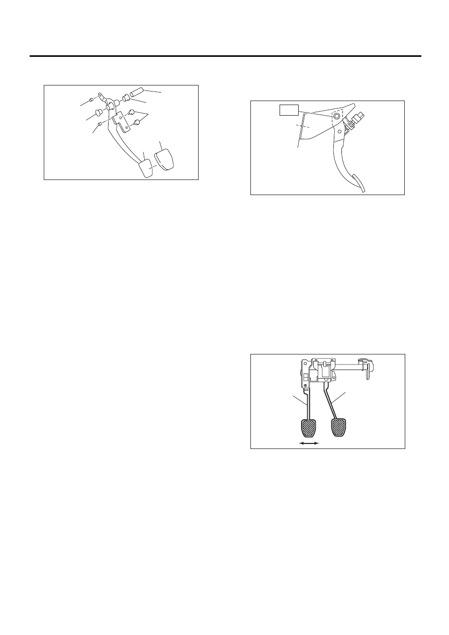
E: INSPECTION
1. CLUTCH PEDAL
Move clutch pedal pads in the lateral direction with
a force of approximately 10 N (1 kgf, 2 lb) to ensure
pedal deflection is in specified range.
If excessive deflection is noted, replace bushings
with new ones.
Deflection of clutch pedal:
Service limit
5.0 mm (0.197 in) or less
(A) Spacer
(B) Bushing
(C) Bushing
(D) Pedal pad
(E) Clutch pedal
(F) Bushing C
( A )
( B )
( B )
( C )
( D )
( E )
( F )
( F )
CL-00130
(A) Clutch pedal
(B) Brake pedal
CL-00185
T
CL-00098
( A )
( B )