Subaru Legacy III (2000-2003 year). Manual - part 644


  Index      Subaru     Subaru Legacy III - service repair manual 2000-2003 year


Search            


Content   ..  642  643  644  645   ..


Subaru Legacy III (2000-2003 year). Manual - part 644


CL-32

CLUTCH SYSTEM

CLUTCH FLUID AIR BLEEDING

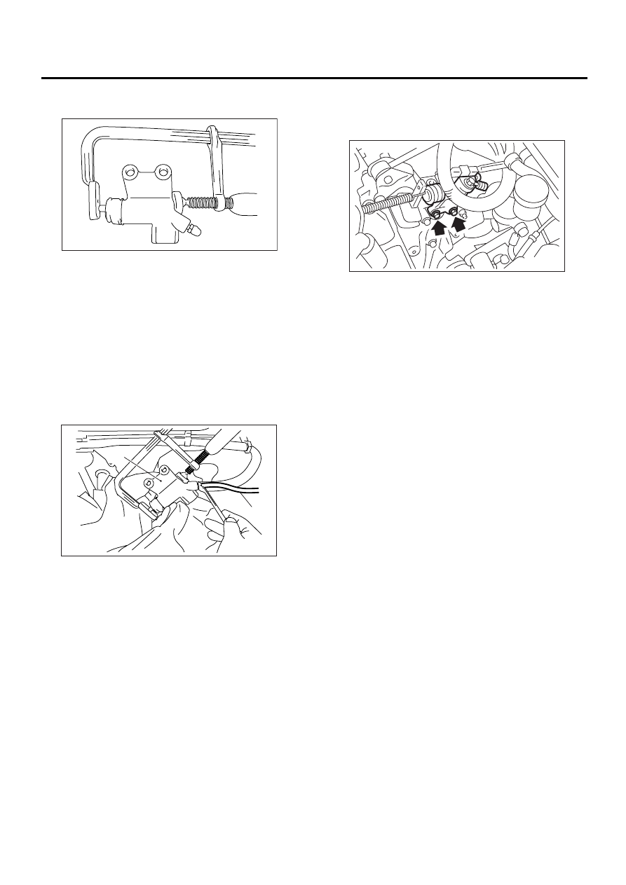
3) Fix the piston with clamp to avoid the piston from
jumping out of cylinder.

4) Fit one end of a vinyl tube into the air bleeder of
operating cylinder and put the other end into a
brake fluid container.
5) Slowly depress the clutch pedal and keep it de-
pressed. Then open the air bleeder to discharge air
together with the fluid.
Release the air bleeder for 1 or 2 seconds. Next,
with the bleeder closed, slowly release the clutch
pedal.

NOTE:
Set the air breather part higher than tip of operating
cylinder when performing this procedure.

6) Repeat these steps until there are no more air
bubbles in the vinyl tube.

CAUTION:
Cover the bleeder with waste cloth when loos-
ening it, to prevent brake fluid from being 
splashed over surrounding parts.
7) Tighten the air bleeder.

Tightening torque:

T: 8 N·m (0.8 kgf-m, 5.8 ft-lb)

8) Install the operation clylinder.

Tightening torque:

T: 37 N·m (3.8 kgf-m, 27.5 ft-lb)

9) After depressing the clutch pedal, make sure
that there are no leaks evident in the entire system.
10) After bleeding air from the system, ensure that
the clutch operates properly.
11) Install the intercooler. <Ref. to IN(H4DOSTC)-
14, INSTALLATION, Intercooler.>

(A) Operating cylinder

(B) Vinyl tube

CL-00069

CL-00070

(B)

(A)

CL-00068

CL-33

CLUTCH SYSTEM

CLUTCH PEDAL

10.Clutch Pedal

A: REMOVAL

1. LHD MODEL

1) Remove steering column. <Ref. to PS-28, RE-
MOVAL, Tilt Steering Column.>
2) Disconnect connectors from stop light and clutch
switches.
3) Remove snap pins which secure lever to push
rod and operating rod.
4) Remove clevis pins which secure lever to push
rod and operating rod.

5) Remove PHV adjusting nut and lock nut.

6) Remove cable clamp, and disconnect PHV ca-
ble from PHV.

NOTE:
Carefully protect boot and inner cable from damage
when disconnecting PHV cable.

7) Remove nut which secures clutch master cylin-
der.

8) Remove bolts and nuts which secure brake and
clutch pedals, and remove pedal assembly.

2. RHD MODEL

1) Disconnect ground cable from battery.
2) Remove lower cover under the stering wheel.
3) Disconnect connector from clutch. (With cruise
control)
4) Remove snap pin and clevis pin that join push
rod and clutch pedal.

(A) Operating rod

(B) Push rod

(C) Snap pin

(D) Clevis pin

(A) Adjusting nut

(B) Lock nut

(C) PHV

CL-00090

( B )

( C )

( D )

( D )

( C )

( A )

CL-00091

( A )

( B )

( C )

(A) PHV cable

(B) Clamp

CL-00092

( A )

( B )

CL-00093

CL-34

CLUTCH SYSTEM

CLUTCH PEDAL

5) Remove master cylinder mounting nuts.

6) Remove PHV adjusting nut and lock nut. (Non-
Turbo model)

7) Remove cable clamp and disconnect PHV cable
from PHV.

NOTE:
Carefully protect boot and inner cable from damage
when disconnecting PHV cable.

8) Remove clutch pedal and bracket as a unit.

B: INSTALLATION

1) Install in the reverse order of removal.

NOTE:
• If cable clamp is damaged, replace it with a new
one.
• Never fail to cover outer cable end with boot.
• Be careful not to kink accelerator cable.
• Always use new clevis pins.
2) Adjust clutch pedal. <Ref. to CL-37, ADJUST-
MENT, Clutch Pedal.>
3) Adjust hill holder. (Non-Turbo model) <Ref. to
BR-49, ADJUSTMENT, Hill Holder.>

C: DISASSEMBLY

1. LHD MODEL

1) Remove clutch switches.
2) Remove clips, assist spring, rod and bushing.

(A)

Master cylinder

(A) Adjusting nut

(B) Lock nut

(C) PHV

(A) PHV cable

(B) Clamp

CL-00074

( A )

CL-00091

( A )

( B )

( C )

CL-00092

( A )

( B )

(A) Clutch pedal bracket

(B) Clutch pedal

(A) Clip

(B) Assist spring

(C) Assist rod

(D) Bushing

(E) Clevis pin

( A )

( B )

CL-00126

CL-00094

( A )

( B )

( C )

( C )

( D )

( D )

( D )

( E )

CL-35

CLUTCH SYSTEM

CLUTCH PEDAL

3) Remove spring pin and lever.

4) Remove clutch pedal and bushings.

5) Remove stopper, clip, O-ring, rod S, and then re-
move spring and bushing S.

6) Remove stoppers from clutch pedal.
7) Remove clutch pedal pad.

2. RHD MODEL

1) Remove clutch switch.
2) Remove clip, pull out clevis pin.

3) Remove assist rod, spring and bushing.
4) Remove clutch pedal from clutch pedal bracket.

5) Remove following parts (B to G) from clutch ped-
al bracket (A) as shown in figure.

(A) Pin

(B) Lever

(A) Clutch pedal

(B) Bushing

(A) Clip (If equipped)

(B) Bushing S (If equipped)

(C) Spring S (If equipped)

(D) Rod S (If equipped)

(E) Stopper

CL-00095

( A )

( B )

CL-00096

( A )

( B )

( B )

CL-00097

( A )

( B )

( C )

( D )

( E )

(A)

Clevis pin

(A) Clutch pedal bracket

(B) Clutch pedal

(A) Clutch pedal bracket

(B) Bushing C

(C) Clip (If equipped)

(D) Bushing S (If equipped)

(E) Spring S (If equipped)

(F) Rod S (If equipped)

(G) Bushing

( A )

CL-00127

( A )

( B )

CL-00128

CL-00184

( A )

( B )

( C )

( D )

( E )

( F )

( G )


Content   ..  642  643  644  645   ..