Subaru Legacy III (2000-2003 year). Manual - part 558
AT-126
AUTOMATIC TRANSMISSION
FRONT DIFFERENTIAL
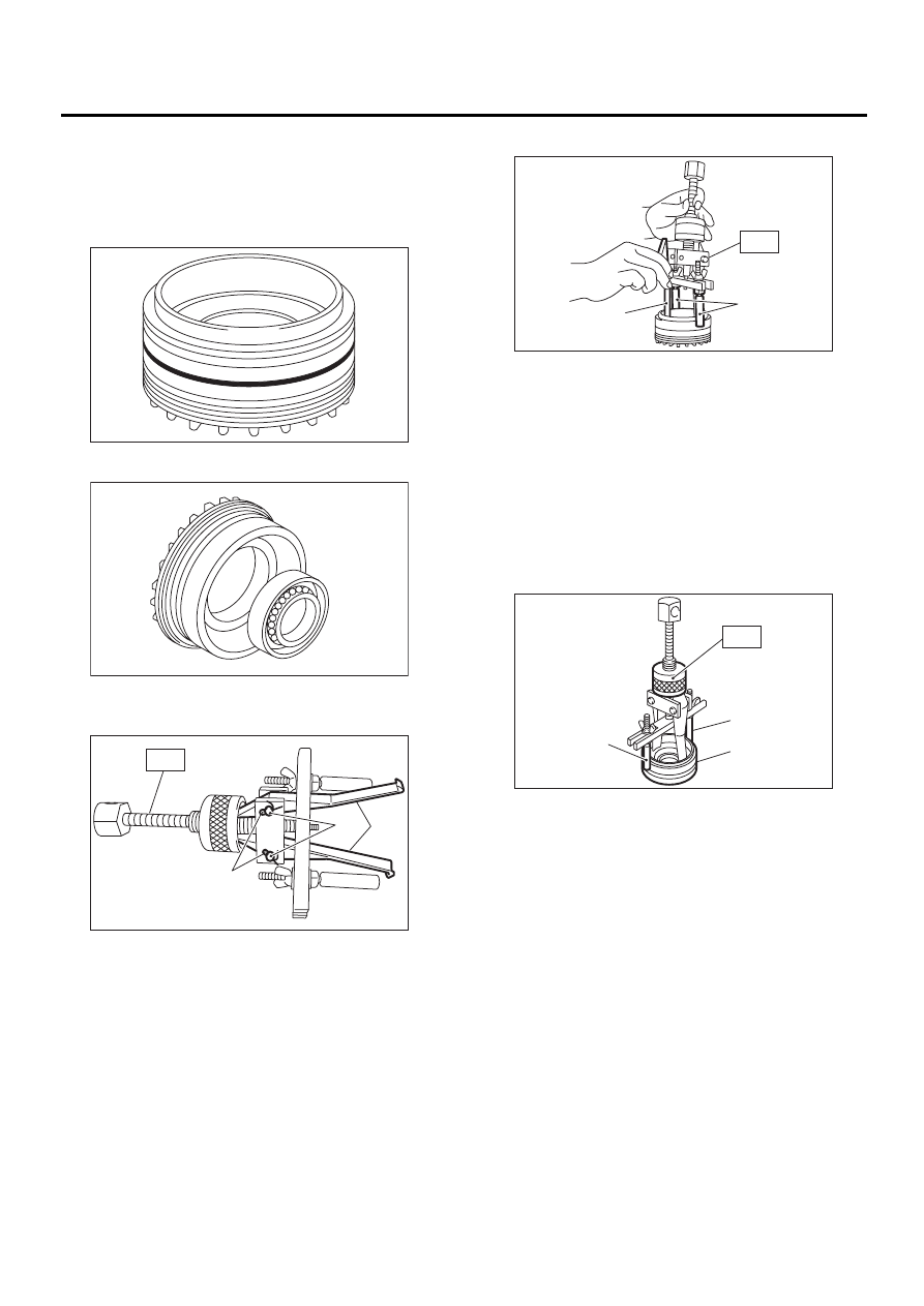
2. SIDE RETAINER
NOTE:
After adjusting the drive pinion backlash and tooth
contact, remove and install the oil seal and O-ring.
1) Remove O-ring.
2) Remove oil seal.
3) Take out either split pin, remove claw.
ST
398527700
PULLER ASSY
4) Securely attach two claws to outer race, set ST
to side retainer.
ST
398527700
PULLER ASSY
5) Return removed claw to the original position,
and install pin and split pin.
6) Hold the shaft of ST to avoid removing from side
retainer, and then remove the bearing outer race.
ST
398527700
PULLER ASSY
NOTE:
Replace bearing inner and outer races as a single
unit.
(A) Claw
(B) Split pin
(C) Pin
AT-00219
AT-00220
AT-00221
ST
( A )
( B )
( C )
(A) Shaft
(B) Claw
(A) Shaft
(B) Side retainer
AT-00222
( A )
( B )
ST
AT-00223
ST
( B )
( A )