Subaru Legacy III (2000-2003 year). Manual - part 478
EN(H4DOSTC)-82
ENGINE (DIAGNOSTICS)
DIAGNOSTIC PROCEDURE WITH DIAGNOSTIC TROUBLE CODE (DTC)
F: DTC P0103 — MASS OR VOLUME AIR FLOW CIRCUIT HIGH INPUT —
• TROUBLE SYMPTOM:
• Erroneous idling
• Engine stalls.
• Poor driving performance
CAUTION:
After repair or replacement of faulty parts, conduct Clear Memory Mode <Ref. to EN(H4DOSTC)-35,
OPERATION, Clear Memory Mode.> and Inspection Mode <Ref. to EN(H4DOSTC)-33, Inspection
Mode.> .
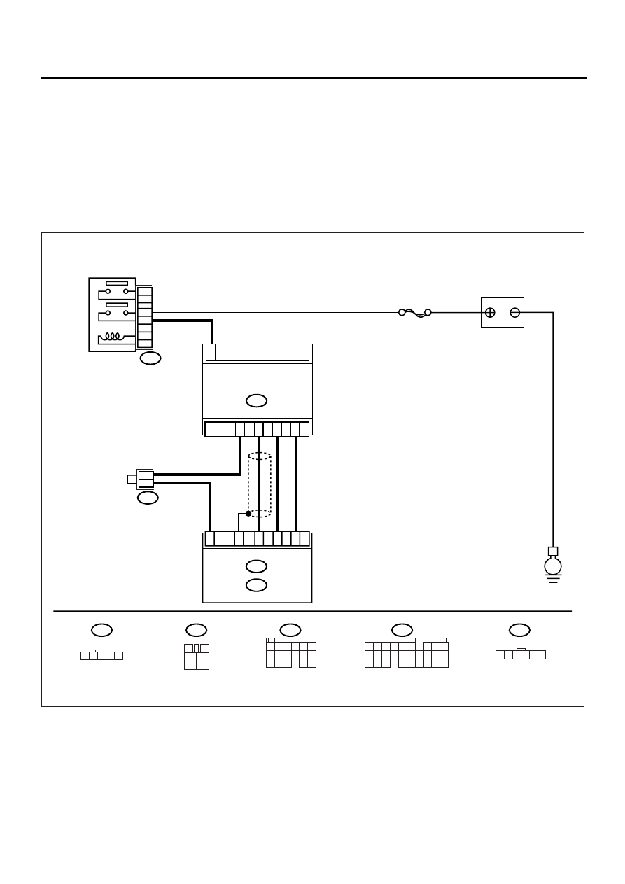
• WIRING DIAGRAM:
EN-00951
B122
B3
B135
5 6
7 8
2
1
9
4
3
10
24
22
23
25
11 12 13 14 15
26 27 28
16 17 18 19
20 21
BATTERY
E
B122
1
B3
MASS AIR FLOW AND
INTAKE AIR TEMPERATURE
ECM
B135
B :
B84
E :
SBF-5
1 2 3 4 5
3
4
1
2
5
6
1 2 3 4 5 6
B84
B47
2
6
2
4
3
5
E7
B27
E13
B19
E8
1 2 3
8 9 10
4
11 12
13 14 15
16
5 6
7
17
MAIN RELAY
B47
1
2
3
5
4
6