Subaru Legacy III (2000-2003 year). Manual - part 456


  Index      Subaru     Subaru Legacy III - service repair manual 2000-2003 year


Search            


Content   ..  454  455  456  457   ..


Subaru Legacy III (2000-2003 year). Manual - part 456


SC(H4DOSTC)-12

STARTING/CHARGING SYSTEMS

STARTER

7. PINION GAP

1) Measure the pinion gap while the pinion is pulled
out as shown in the figure.

Pinion gap:

0.5 — 2.0 mm (0.020 — 0.079 in)

If the motor is running with the pinion forced end-
wise on shaft, disconnect the connector from termi-
nal M of switch assembly, and then connect termi-
nal M to ground terminal (

) of battery with a lead

wire. Next, gently push the pinion back with your
fingertips, and then measure the pinion gap.
2) If the pinion gap is outside specified range, re-
move or add number of adjustment washers used
on the mounting surface of switch assembly until
correct pinion gap is obtained.
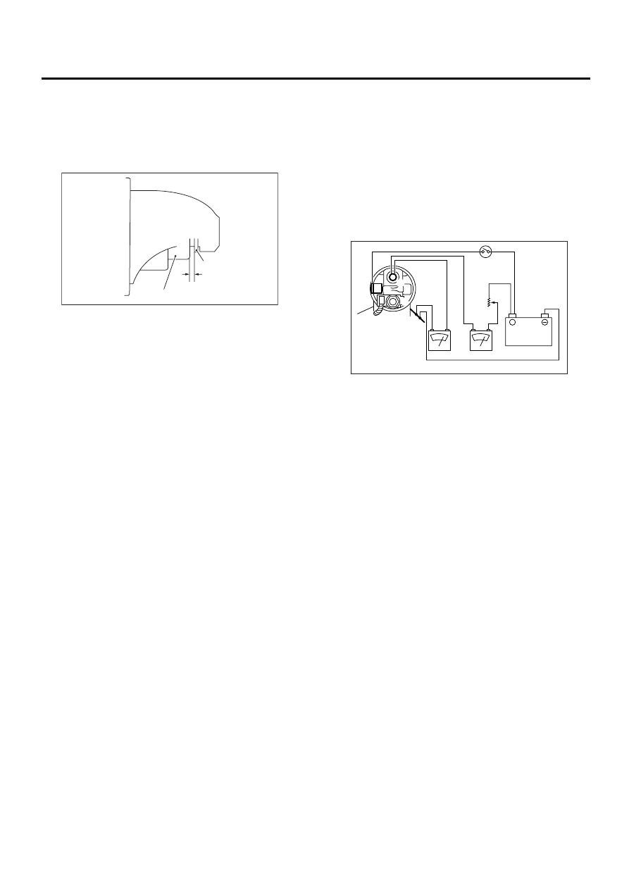
8. PERFORMANCE TEST

The starter should be submitted to performance
tests whenever it has been overhauled, to assure
its satisfactory performance when installed on the
engine.
Three performance tests, no-load test, load test,
and lock test, are presented here; however, if the
load test and lock test cannot be performed, carry
out at least the no-load test.
For these performance tests, use the circuit shown
in figure.

1) No-load test
With switch on, adjust the variable resistance to ob-
tain 11 V, take the ammeter reading, and then mea-
sure the starter speed. Compare these values with
the specifications.

No-load test (Standard):

Voltage / Current

MAX. 11 V / 90 A

Rotating speed

MT vehicles

2,800 rpm or more

AT vehicles

2,400 rpm or more

(A) Pinion

(B) Gap

(C) Stopper

SC-00027

( A )

( B )

( C )

(A) Variable resistance

(B) Magnetic switch

(C) Starter body

SC-00077

(A)

(B)

(C)

12V

+

A

V

B

S

M

SC(H4DOSTC)-13

STARTING/CHARGING SYSTEMS

STARTER

2) Load test
Apply the specified braking torque to starter. The
condition is satisfactory if the current draw and
starter speed are within the specifications.

Load test (Standard):

Voltage / Road

MT vehicles

7.5 V / 8.6 N (0.88 kgf, 1.94 lb)

AT vehicles

7.7 V / 16.0 N (1.63 kgf, 3.59 lb)

Current / Speed

MT vehicles

300 A / 920 rpm or more

AT vehicles

400 A / 740 rpm or more

3) Lock test
With the starter stalled, or not rotating, measure the
torque developed and current draw when the volt-
age is adjusted to the specified voltage.

Lock test (Standard):

Voltage / Current

MT vehicles

4 V / 650 A or less

AT vehicles

3.5 V / 940 A or less

Torque

MT vehicles

14.7 N·m (1.50 kgf-m, 10.8 ft-lb) or more

AT vehicles

28.9 N·m (2.95 kgf-m, 21.3 ft-lb) or more

SC(H4DOSTC)-14

STARTING/CHARGING SYSTEMS

GENERATOR

3. Generator

A: REMOVAL

1) Disconnect the ground cable from battery.

2) Disconnect the connector and terminal from
generator.
3) Remove the V-belt cover.
4) Remove the front side V-belt. 
<Ref. to ME(H4DOSTC)-42, REMOVAL, V-belt.>
5) Remove the bolts which install generator onto
bracket. 

B: INSTALLATION

Install in the reverse order of removal.

CAUTION:
Check and adjust the V-belt tension. <Ref. to 
ME(H4DOSTC)-43, INSPECTION, V-belt.>

C: DISASSEMBLY

1) Remove the four through-bolts.
2) Heat the portion (A) of rear cover to 50

°

C

(122

°

F) with heater drier.

3) Then insert the tip of a flat tip screwdriver into the
gap between stator core and front cover. Pry them
apart to disassemble.

4) Hold the rotor with a vise and remove pulley nut.

FU-00009

SC-00032

SC-00032

(A) Screwdriver

SC-00079

(A)

SC-00080

(A)

(A)

SC-00035

SC(H4DOSTC)-15

STARTING/CHARGING SYSTEMS

GENERATOR

CAUTION:
When holding the rotor with vise, insert alumi-
num plates or wood pieces on the contact sur-
faces of vise to prevent rotor from damage.

5) Remove the ball bearing as follows.

(1) Remove the bolt, and then remove the bear-
ing retainer.

(2) Firmly install an appropriate tool (such as a
fit socket wrench) to bearing inner race.

(3) Push the ball bearing off the front cover us-
ing a press.

6) Remove the bearing from rotor using a bearing
puller.

D: ASSEMBLY

To assemble, reverse order of disassembly.
1) Pulling up brush
Before assembling, press the brush down into
brush holder, and then fix them in that position by
passing a [1 mm (0.08 in) dia. length 4 to 5 cm (1.6
to 2.0 in)] wire through the hole shown in the figure.

CAUTION:
Be sure to remove the wire after reassembly.

2) Install the ball bearing.

(1) Set the ball bearing on the front cover, and
then securely install an appropriate tool (such as
a fit socket wrench) to the bearing outer race.
(2) Press the ball bearing into the specified po-
sition using a press.
(3) Install the bearing retainer.

3) Press the bearing (rear side) into the rotor shaft
using a press to install.
4) Heat the bearing box in rear cover [50 to 60

°

C

(122 to 140

°

F)], and then press the rear bearing

into rear cover.

CAUTION:
Grease should not be applied to rear bearing. 
Remove the oil completely if it is found on bear-
ing box.
5) After reassembly, turn the pulley by hand to
check that rotor turns smoothly.

(A) Front cover

(B) Pulley

(C) Nut

(D) Rotor

( A )

( B )

( C )

( D )

SC-00036

SC-00161

SC-00082

(A) Wire

SC-00046

SC-00092

(A)


Content   ..  454  455  456  457   ..