Subaru Legacy III (2000-2003 year). Manual - part 430
ME(H4DOSTC)-84
MECHANICAL
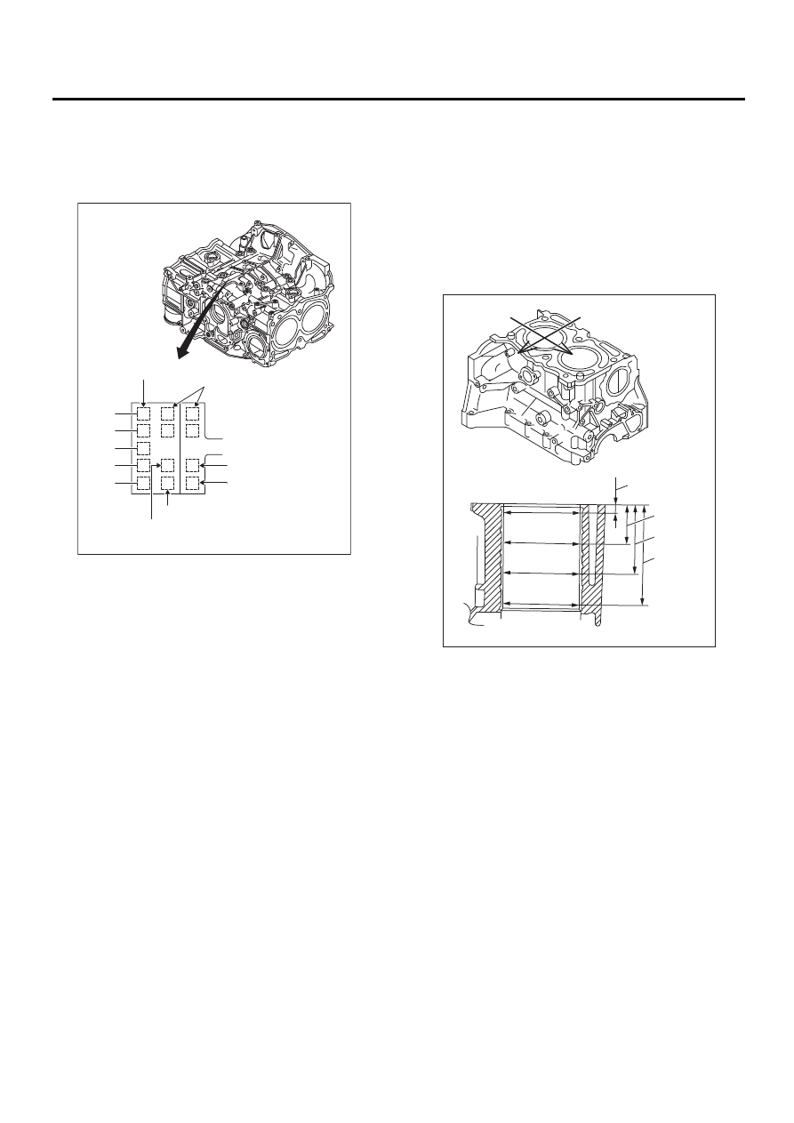
CYLINDER BLOCK
Standard diameter:
A: 92.005 — 92.015 mm (3.6222 — 3.6226
in)
B: 91.995 — 92.005 mm (3.6218 — 3.6222
in)
2) How to measure the inner diameter of each cyl-
inder:
Measure the inner diameter of each cylinder in both
the thrust and piston pin directions at the heights
shown in the figure, using a cylinder bore gauge.
NOTE:
Measurement should be performed at a tempera-
ture of 20
°
C (68
°
F).
Taper:
Standard
0.015 mm (0.0006 in)
Limit
0.050 mm (0.0020 in)
Out-of-roundness:
Standard
0.010 mm (0.0004 in)
Limit
0.050 mm (0.0020 in)
3) When the piston is to be replaced due to general
or cylinder wear, determine a suitable sized piston
by measuring the piston clearance.
4) How to measure the outer diameter of each pis-
ton:
Measure the outer diameter of each piston at the
height shown in the figure. (Thrust direction)
NOTE:
Measurement should be performed at a tempera-
ture of 20
°
C (68
°
F).
(A) Main journal size mark
(B) Cylinder block RH-LH combination mark
(C) #1 cylinder bore size mark
(D) #2 cylinder bore size mark
(E) #3 cylinder bore size mark
(F) #4 cylinder bore size mark
ME-00170
#4
#5
#3
#2
#1
5
4
5
4
A
B
A
B
( B )
( C )
( D )
( E )
( F )
( A )
(A) Piston pin direction
(B) Thrust direction
H1: 10 mm (0.39 in)
H2: 45 mm (1.77 in)
H3: 80 mm (3.15 in)
H4: 115 mm (4.53 in)
ME-00171
H1
H2
H3
H4
( A )
( B )