Subaru Legacy III (2000-2003 year). Manual - part 428
ME(H4DOSTC)-76
MECHANICAL
CYLINDER BLOCK
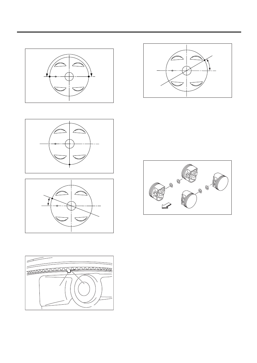
11) Position the second ring gap at 180
°
on the re-
verse side for the top ring gap.
12) Position the expander rail gap at (C) in the fig-
ure.
NOTE:
Align the lower rail spin stopper (F) with piston side
surface hole (E).
13) Position the upper rail gap at (G) in the figure.
NOTE:
• Ensure ring gaps do not face the same direction.
• Ensure ring gaps are not within the piston skirt
area.
14) Installing the circlip:
Install the circlips in piston holes located opposite
of the service holes in cylinder block, when posi-
tioning all pistons in the corresponding cylinders.
NOTE:
Use new circlips.
ME-00635
180˚
(A)
(B)
ME-00636
(C)
ME-00637
(D)
25˚
ME-00152
( E )
( F )
ME-00638
(G)
30
˚
ME-00154
Front side
#1
#3
#4
#2