Subaru Legacy III (2000-2003 year). Manual - part 316
EN(H6DO)-66
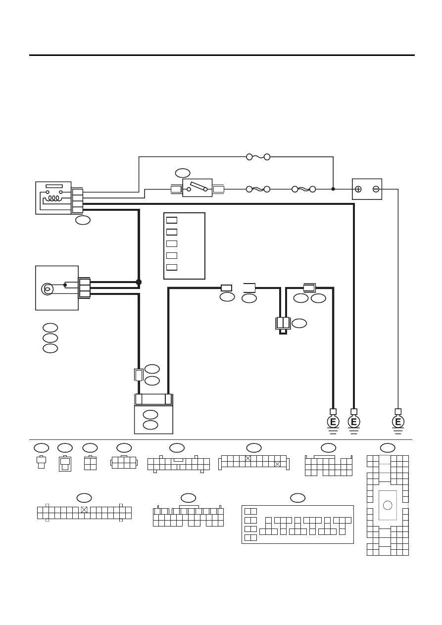
ENGINE (DIAGNOSTICS)
ENGINE MALFUNCTION INDICATOR LAMP (MI)
E: CHECK ENGINE MALFUNCTION INDICATOR LAMP (MI) DOES NOT BLINK
AT A CYCLE OF 3 HZ.
• DIAGNOSIS:
• The CHECK ENGINE malfunction indicator lamp (MI) circuit is open or shorted.
• Test mode connector circuit is open.
• TROUBLE SYMPTOM:
• When inspection mode, MI does not blink at a cycle of 3 Hz.
• WIRING DIAGRAM:
EN-01081
LHD : 9
RHD : 38
LHD : 13
RHD : 36
LHD : 11
RHD : 34
LHD : 10
RHD : 37
LHD : C11
RHD : B10
B:
i11
C:
i12
IGNITION
RELAY
SBF-4
No. 5
SBF-1
4
1
B157
B72
IGNITION
SWITCH
BATTERY
B36
B4 B5 B6
A4 A5 A6
C5 C6
F6
D4 D5 D6
F1
H1
C4
G6
G1
C2
K1
M1 M2
K6
L1
D1 D2
A1 A2
B1 B2
I6
J6
L2
I1
J1
H6
M4 M5 M6
L4 L5 L6
N5 N6
O4 O5 O6
N4
P4 P5
N2
O1 O2
P1 P2
N3
O3
P3
P6
A3
B3
C3
E4 E5 E6
E1 E2
B134
B157
10
11 12 13
14 15 16
17
18
19
20
21 22 23
24 25 26
27
28
29
30
31 32 33
34 35 36
37
38
1 2
9
3 4
5 6
7 8
B72
3 4
1 2
B75
B76
1
2
1
2
B137
1
1
B36
i1
B75
B76
B83
A4
B252
E49
D15
A5
D: B137
A: B134
ECM
18
15
2
B252
1 2 3 4
5 6 7 8
1 2 3 4
10 11 12
19 20 21
13
5
6
14 15
7
8 9
16 17
18
22
1
2
7
8
9
5
6
3
4
10 11 12
19 20 21
29 30 31
13 14 15 16 17
27 28
18
22 23 24 25 26
COMBINATION
METER
A:
i10
i10
1 2 3 4 5 6 7
8 9 10 11 12 13 14
15 16 17 18 19 20 21 22 23 24 25 26 27 28 29 30
A8
B5
i12
1 2 3
8
9 10
4
11 12 13
14 15 16
5 6 7
17 18
B83
1 2 3 4
5 6 7 8 9 10
11 12
19
20
13 14 15 16 17 18
1
*
2
*
3
*
4
*
5
*
1
*
2
*
3
*
4
*
5
*