Subaru Legacy III (2000-2003 year). Manual - part 1002


  Index      Subaru     Subaru Legacy III - service repair manual 2000-2003 year


Search            


Content   ..  1000  1001  1002  1003   ..


Subaru Legacy III (2000-2003 year). Manual - part 1002


CC-28

CRUISE CONTROL SYSTEM (DIAGNOSTICS)

DIAGNOSTICS CHART WITH TROUBLE CODE

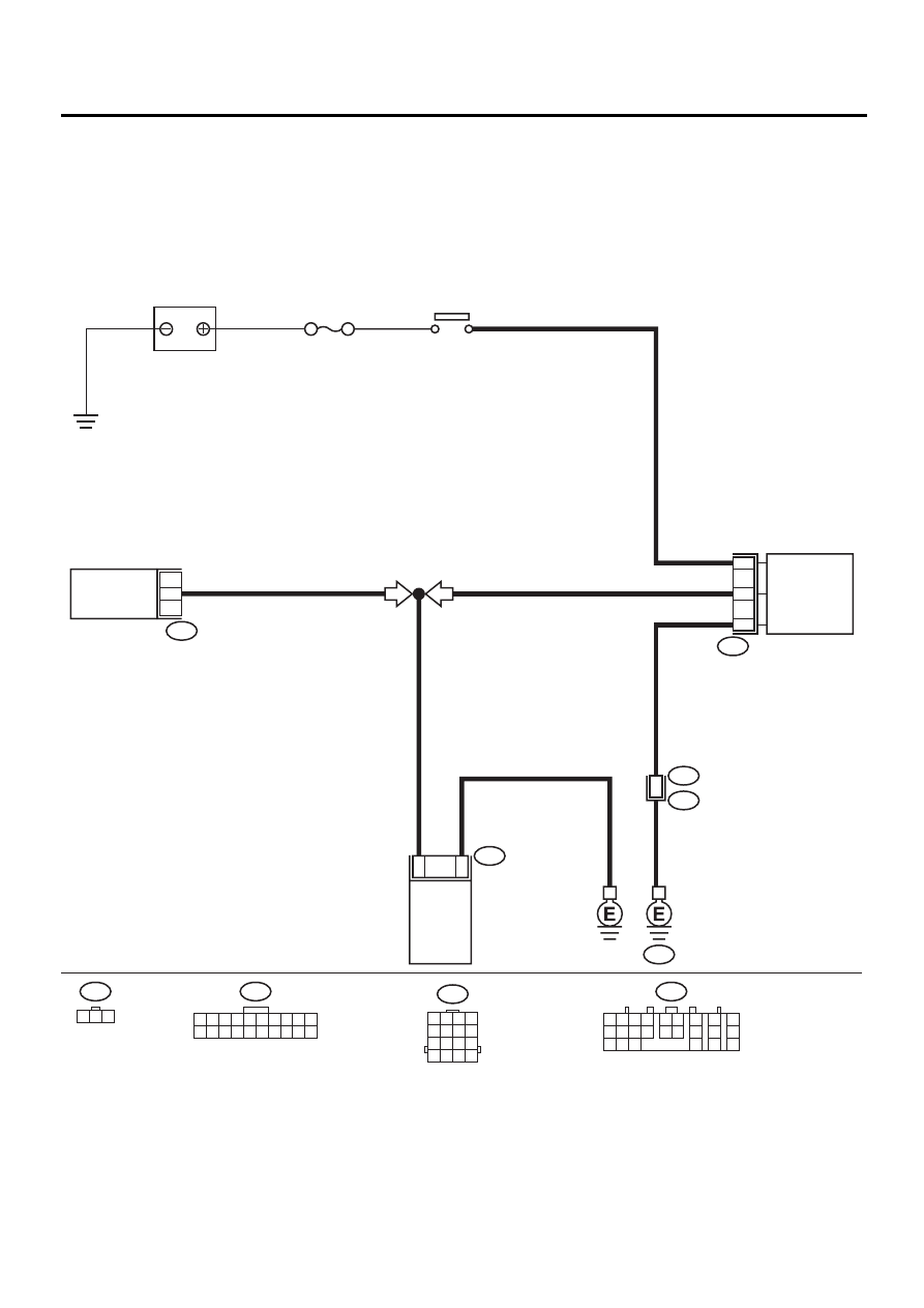
B: DTC 22 VEHICLE SPEED SENSOR

DIAGNOSIS:
Disconnection or short circuit of vehicle speed sensor system.
TROUBLE SYMPTOM:
Cruise control cannot be set. (Cancelled immediately.)
WIRING DIAGRAM:

CRUISE

CONTROL

MODULE

B17

B94

GE

3

1

2

BATTERY

M/B NO. 5

C17

AT

19

6

B94

1 2 3 4 5 6 7 8 9 10

11 12 13 14 15 16 17 18 19 20

IGNITION 

RELAY

VEHICLE SPEED

SENSOR (MT)

B56

C:

TRANSMISSION

CONTROL

MODULE

MT

B17

1 2 3

B56

C:

CC-00099

16

B22

E3

B22

1 2 3 4
5 6 7 8
9 10 11 12

13 14 15 16

1 2

7

8

9

5 6

3 4

10 11 12
19 20 21

13

14 15

16

17

18

22

23

24

CC-29

CRUISE CONTROL SYSTEM (DIAGNOSTICS)

DIAGNOSTICS CHART WITH TROUBLE CODE

Step

Value

Yes

No

1

CHECK TRANSMISSION TYPE.
Is the transmission type MT?

Transmission type is MT.

Go to step 2.

Go to step 6.

2

CHECK HARNESS BETWEEN BATTERY 
AND VEHICLE SPEED SENSOR.
1) Turn ignition switch to OFF.
2) Disconnect harness connector from vehicle 

speed sensor.

3) Turn ignition switch to ON.
4) Measure voltage between vehicle speed 

sensor harness connector terminal and 
chassis ground.

Connector & terminal

(B17) No. 3 (+) — Chassis ground (

−−−−

):

Does the measured value exceed the spec-
ified value?

10 V

Go to step 3.

Check harness for 
open or short 
between ignition 
relay and vehicle 
speed sensor.

3

CHECK HARNESS BETWEEN CRUISE CON-
TROL MODULE AND VEHICLE SPEED SEN-
SOR.
1) Turn ignition switch to OFF.
2) Disconnect harness connector from cruise 

control module.

3) Measure resistance between vehicle speed 

sensor harness connector terminal and 
cruise control module harness connector 
terminal.

Connector & terminal

(B17) No. 1 — (B94) No. 19:

Is the measured value less than the speci-
fied value?

10 

Go to step 4.

Repair harness.

4

CHECK HARNESS BETWEEN VEHICLE 
SPEED SENSOR AND ENGINE GROUND.
Measure resistance between vehicle speed 
sensor harness connector terminal and engine 
ground.

Connector & terminal

(B17) No. 2 (+) — Engine ground (

−−−−

):

Is the measured value less than the specified 
value?

10 

Go to step 5.

Repair harness.

5

CHECK VEHICLE SPEED SENSOR.
1) Connect harness connector to vehicle 

speed sensor.

2) Lift-up the vehicle and support with safety 

stands.

3) Drive the vehicle at speed greater than 20 

km/h (12 MPH).

Warning:

Be careful not to be caught up by the run-
ning wheels.

4) Measure voltage between cruise control 

module harness connector terminal and 
chassis ground.

Connector & terminal

(B94) No. 19 (+) — Chassis ground (

−−−−

):

Is the measured value same as the speci-
fied value?

←→

 5 V

Replace cruise 
control module.  
<Ref. to CC-6, 
Cruise Control 
Module.>

Replace vehicle 
speed sensor.

CC-30

CRUISE CONTROL SYSTEM (DIAGNOSTICS)

DIAGNOSTICS CHART WITH TROUBLE CODE

6

CHECK HARNESS BETWEEN CRUISE CON-
TROL MODULE AND TRANSMISSION CON-
TROL MODULE.
1) Turn ignition switch to OFF.
2) Disconnect harness connector from trans-

mission control module and cruise control 
module.

3) Measure resistance between cruise control 

module harness connector terminal and 
transmission control module harness con-
nector terminal.

Connector & terminal

(B94) No. 19 — (B56) No. 17:

Is the measured value less than the speci-
fied value?

10 

?

Go to step 7.

Repair harness.

7

CHECK TRANSMISSION CONTROL MOD-
ULE.
1) Connect harness connector to transmission 

control module.

2) Lift-up the vehicle and support with safety 

stands.

3) Drive the vehicle faster than 10 km/h (6 

MPH).

Warning:

Be careful not to be caught by the running
wheels.

4) Measure voltage between transmission 

control module harness connector terminal 
and chassis ground.

Connector & terminal

(B56) No. 17 (+) — Chassis ground (

−−−−

):

Is the measured value same as the speci-
fied value?

←→

 5 V

Replace cruise 
control module. 
<Ref. to CC-6, 
Cruise Control 
Module.> 

Replace transmis-
sion control mod-
ule. <Ref. to AT-
76, Transmission 
Control Module 
(TCM).> 

Step

Value

Yes

No

CC-31

CRUISE CONTROL SYSTEM (DIAGNOSTICS)

DIAGNOSTICS CHART WITH TROUBLE CODE

C: DTC 28 WIRING HARNESS OPENED.

Step

Value

Yes

No

1

CHECK BATTERY.
Measure battery specific gravity of electrolyte.
Does the measured value exceed the specified 
value?

1.250

Go to step 2.

Charge or replace 
battery. Go to step 
2.

2

CHECK FUSES, CONNECTORS AND HAR-
NESSES.
Check the condition of the main and other 
fuses, and harnesses and connectors. Also 
check for proper grounding.
Is there anything unusual about the appear-
ance of main fuse, fuse, harness, connector 
and grounding?

Fuse, harness, connector and 
grounding are OK.

End of inspection. Repair or replace 

faulty parts.


Content   ..  1000  1001  1002  1003   ..