Subaru Legacy III (2000-2003 year). Manual - part 95
SC(H4SO)-14
STARTING/CHARGING SYSTEMS
GENERATOR
3. Generator
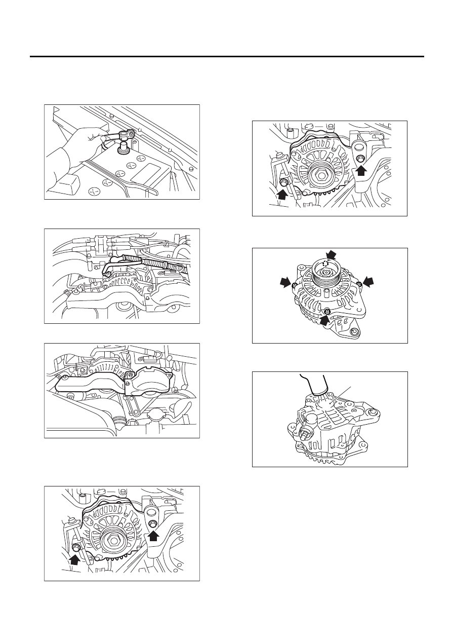
A: REMOVAL
1) Disconnect the ground cable from battery.
2) Disconnect the connector and terminal from
generator.
3) Remove the V-belt cover.
4) Remove the front side V-belt.
<Ref. to ME(H4SO)-41, REMOVAL, V-belt.>
5) Remove the bolts which install generator onto
bracket.
B: INSTALLATION
Install in the reverse order of removal.
CAUTION:
Check and adjust the V-belt tension. <Ref. to
ME(H4SO)-42, INSPECTION, V-belt.>
C: DISASSEMBLY
1) Remove the four through-bolts.
2) Heat the portion (A) of rear cover to 50
°
C
(122
°
F) with heater drier.
FU-00009
SC-00029
SC-00031
SC-00032
SC-00032
SC-00078
SC-00079
(A)