Subaru Legacy III (2000-2003 year). Manual - part 93
SC(H4SO)-6
STARTING/CHARGING SYSTEMS
STARTER
2. Starter
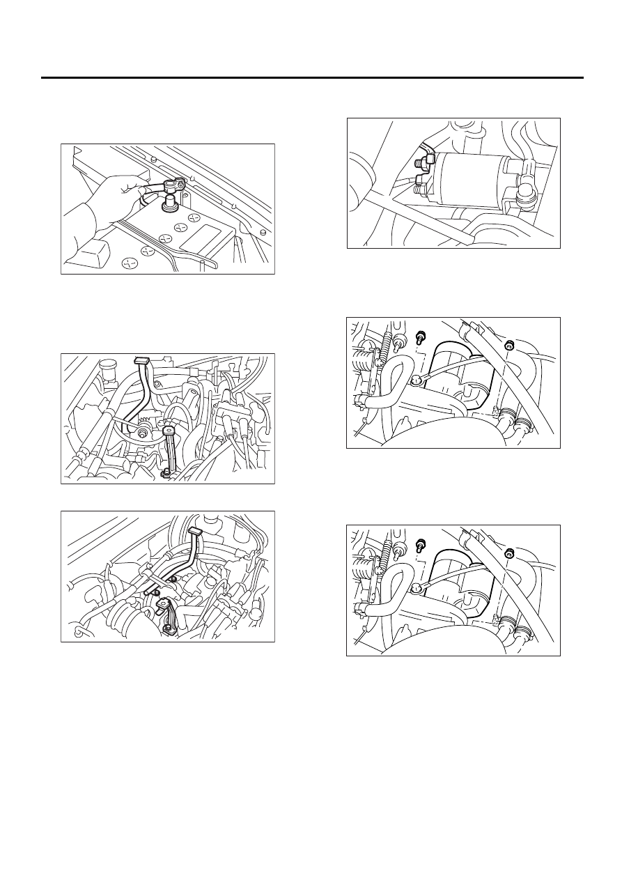
A: REMOVAL
1) Disconnect the ground cable from battery.
2) Remove the air cleaner case.
<Ref. to IN(H4SO)-6, REMOVAL, Air Cleaner
Case.>
3) Remove the air cleaner case stay.
• MT vehicles
• AT vehicles
4) Disconnect the connector and terminal from
starter.
5) Remove the starter from transmission.
B: INSTALLATION
Install in the reverse order of removal.
Tightening torque:
50 N·m (5.1 kgf-m, 37 ft-lb)
FU-00009
SC-00004
SC-00005
(A) Terminal
(B) Connector
SC-00006
( A )
( B )
SC-00007
SC-00007