Subaru Legacy III (2000-2003 year). Manual - part 59


  Index      Subaru     Subaru Legacy III - service repair manual 2000-2003 year


Search            


Content   ..  57  58  59  60   ..


Subaru Legacy III (2000-2003 year). Manual - part 59


ME(H4SO)-48

MECHANICAL

TIMING BELT ASSEMBLY

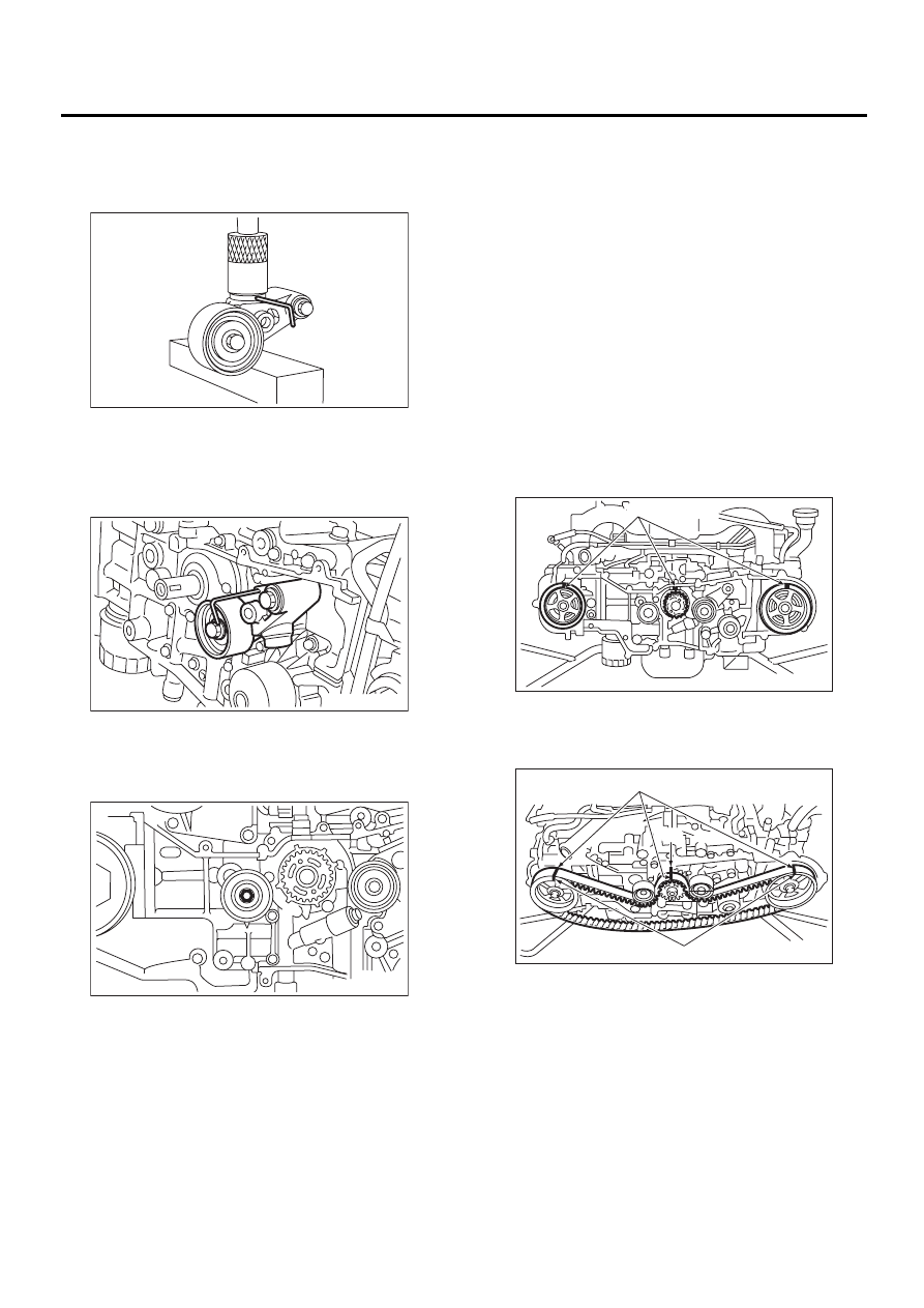
(3) With a 2 mm (0.08 in) dia. stopper pin or a 2
mm (0.08 in) (nominal) dia. hex bar wrench in-
serted into the stopper pin hole in the cylinder,
secure the adjuster rod.

2) Install the automatic belt tension adjuster as-
sembly.

Tightening torque:

39 N·m (4.0 kgf-m, 28.9 ft-lb)

3) Install the belt idler (No. 1).

Tightening torque:

39 N·m (4.0 kgf-m, 28.9 ft-lb)

2. TIMING BELT

1) Preparation for the installation of automatic belt
tension adjuster assembly. <Ref. to ME(H4SO)-47,
AUTOMATIC BELT TENSION ADJUSTER AS-
SEMBLY AND BELT IDLER, INSTALLATION,
Timing Belt Assembly.>
2) Installation of timing belt

(1) Turn the camshaft sprocket No. 2 using
ST1, and then turn the camshaft sprocket No. 1
using ST2 so that their alignment marks (A)
come to top positions.

ST1

18231AA010 CAMSHAFT SPROCKET 

WRENCH

NOTE:
Also the CAMSHAFT SPROCKET WRENCH
(499207100) can be used.
ST2

499207400

CAMSHAFT SPROCKET 
WRENCH

(2) While aligning alignment marks (B) on the
timing belt with marks (A) on sprockets, position
the timing belt properly.

3) Install the belt idler No. 2.

Tightening torque:

39 N·m (4.0 kgf-m, 28.9 ft-lb)

ME-00437

ME-00241

ME-00242

( A )

ME-00243

ME-00244

( A )

( A )

( B )

ME(H4SO)-49

MECHANICAL

TIMING BELT ASSEMBLY

4) Install the belt idler (No. 2).

Tightening torque:

39 N·m (4.0 kgf-m, 28.9 ft-lb)

5) After ensuring that the marks on timing belt and
camshaft sprockets are aligned, remove the stop-
per pin from belt tensioner adjuster.

6) Install the timing belt guide. (MT vehicles)

(1) Temporarily tighten the remaining bolts.

(2) Check and adjust the clearance between
timing belt and timing belt guide by using thick-
ness gauge.

Clearance:

1.0

±±±±

0.5 mm (0.039

±±±±

0.020 in)

(3) Tighten the remaining bolts.

Tightening torque:

10 N·m (1.0 kgf-m, 7.2 ft-lb)

7) Install the belt cover. <Ref. to ME(H4SO)-45, IN-
STALLATION, Belt Cover.>
8) Install the crankshaft pulley. <Ref. to
ME(H4SO)-43, INSTALLATION, CRANKSHAFT
PULLEY.>
9) Install the V-belt. <Ref. to ME(H4SO)-42, IN-
STALLATION, V-belt.>

ME-00235

ME-00245

ME-00230

ME-00246

ME-00247

ME(H4SO)-50

MECHANICAL

TIMING BELT ASSEMBLY

C: INSPECTION

1. TIMING BELT

1) Check the timing belt teeth for breaks, cracks,
and wear. If any fault is found, replace the belt. 
2) Check the condition of back side of belt; if any
crack is found, replace the belt.

NOTE:
• Be careful not to let oil, grease or coolant contact
the belt. Remove quickly and thoroughly if this hap-
pens.
• Do not bend the belt sharply.

Bending radius: h

60 mm (2.36 in) or more

2. AUTOMATIC BELT TENSION ADJUST-
ER

1) Visually check oil seals for leaks, and rod ends
for abnormal wear or scratches. If necessary, re-
place faulty parts.
2) Check that the adjuster rod does not move when
a pressure of 294 N (30 kgf, 66 lb) is applied to it.
This is to check adjuster rod stiffness.
3) If the adjuster rod is not stiff and moves freely
when applying 294 N (30 kgf, 66 lb), check it using
the following procedures:

(1) Slowly press the adjuster rod down to the
end surface of the cylinder. Repeat this motion 2
or 3 times.
(2) With the adjuster rod moved all the way up,
apply a pressure of 294 N (30 kgf, 66 lb) to it.
Check adjuster rod stiffness.
(3) If the adjuster rod is not stiff and moves
down, replace the automatic belt tension adjust-
er assembly with a new one.

NOTE:
• Always use a vertical type pressing tool to move
the adjuster rod down.
• Do not use a lateral type vise.
• Push the adjuster rod vertically.
• Press-in the adjuster rod gradually taking more
than 3 minutes.
• Do not allow press pressure to exceed 9,807 N
(1,000 kgf, 2,205 lb).

• Press the adjuster rod as far as the end surface
of the cylinder. Do not press the adjuster rod into
the cylinder. Doing so may damage the cylinder.
4) Measure the extension of rod beyond the body.
If it is not within specifications, replace with a new
one.

Rod extension: H

5.7

±±±±

0.5 mm (0.224

±±±±

0.020 in)

3. BELT TENSION PULLEY

1) Check the mating surfaces of timing belt and
contact point of adjuster rod for abnormal wear or
scratches. Replace the automatic belt tension ad-
juster assembly if faulty.
2) Check the tension pulley for smooth rotation.
Replace if noise or excessive play is noted.
3) Check the tension pulley for grease leakage.

4. BELT IDLER

1) Check the belt idler for smooth rotation. Replace
if noise or excessive play is noted.
2) Check the belt outer contacting surfaces of idler
pulley for abnormal wear and scratches.
3) Check the belt idler for grease leakage.

ME-00248

h

ME-00249

H

ME(H4SO)-51

MECHANICAL

CAMSHAFT SPROCKET

16.Camshaft Sprocket

A: REMOVAL

1) Remove the V-belt. <Ref. to ME(H4SO)-41, RE-
MOVAL, V-belt.>
2) Remove the crankshaft pulley. <Ref. to
ME(H4SO)-43, REMOVAL, Crankshaft Pulley.>
3) Remove the belt cover. <Ref. to ME(H4SO)-45,
REMOVAL, Belt Cover.>
4) Remove the timing belt assembly. <Ref. to
ME(H4SO)-46, REMOVAL, Timing Belt Assem-
bly.>
5) Remove the camshaft position sensor. <Ref. to
FU(H4SO)-28, REMOVAL, Camshaft Position
Sensor.>
6) Remove the camshaft sprocket No. 2. To lock
the camshaft, use ST.
ST

18231AA010

CAMSHAFT SPROCKET 
WRENCH

NOTE:
Also the CAMSHAFT SPROCKET WRENCH
(499207100) can be used.

7) Remove the camshaft sprocket No. 1. To lock
the camshaft, use ST.
ST

499207400

CAMSHAFT SPROCKET 
WRENCH

B: INSTALLATION

1) Install the camshaft sprocket No. 1. To lock the
camshaft, use ST.
ST

499207400

CAMSHAFT SPROCKET 
WRENCH

Tightening torque:

78 N·m (8.0 kgf-m, 57.9 ft-lb)

NOTE:
Do not confuse the right and left side camshaft
sprockets during installation. The camshaft sprock-
et No. 2 is identified by a projection used to monitor
camshaft position sensor.

2) Install the camshaft sprocket No. 2. To lock cam-
shaft, use ST.
ST

18231AA010

CAMSHAFT SPROCKET 
WRENCH

NOTE:
Also the CAMSHAFT SPROCKET WRENCH
(499207100) can be used.

Tightening torque:

78 N·m (8.0 kgf-m, 57.9 ft-lb)

3) Install the camshaft position sensor. <Ref. to
FU(H4SO)-28, INSTALLATION, Camshaft Position
Sensor.>
4) Install the timing belt assembly. <Ref. to
ME(H4SO)-47, INSTALLATION, Timing Belt As-
sembly.>
5) Install the belt cover. <Ref. to ME(H4SO)-45, IN-
STALLATION, Belt Cover.>

ME-00250

ST

ST

ME-00251

ST

ME-00251

ME-00250

ST


Content   ..  57  58  59  60   ..