Subaru Impreza 3 / Impreza WRX / Impreza WRX STI. Manual - part 796


  Index      Subaru     Subaru Impreza 3 / Impreza WRX / Impreza WRX STI - service repair manual 2008-2014 year


Search            


Content   ..  794  795  796  797   ..


Subaru Impreza 3 / Impreza WRX / Impreza WRX STI. Manual - part 796


WI-13

Basic Diagnostic Procedure

WIRING SYSTEM

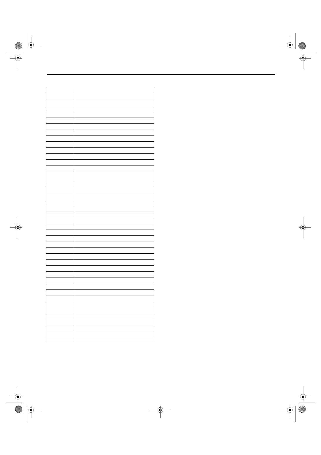
F: ABBREVIATION IN WIRING DIAGRAMS

Abbr.

Full name

ABS

Anti-lock Brake System

ACC

Accessory

A/C

Air Conditioner

ASSY

Assembly

A/F

Air/Fuel (Air fuel ratio sensor)

AUX

Auxiliary Audio Input Terminal

B

Battery

CAN

Controller Area Network

CM

Control Module

DN

Down

DCCD

Driver’s Control Center Differential

E

Ground

ECM

Engine Control Module

EEPROM

Electrically Erasable Programmable Read-
Only Memory

ELCM

Evaporative Leak Check Module

F/B

Fuse & Relay Box

FL

Front Left

FR

Front Right

G

Gravity (G sensor)

H/L

Headlight

HI

High

I/F

Interface

IG

Ignition

INT

Intermittent

LCD

Liquid Crystal Display

LH

Left Hand

LO

Low

M

Motor

M/B

Main Fuse Box

PASS

Passing

RH

Right Hand

RL

Rear Left

RR

Rear Right

SBF

Slow Blow Fuse

SI-DRIVE

SUBARU Intelligent Drive

ST

Starter

SW

Switch

TPMS

Tire Pressure Monitor System

VDC

Vehicle Dynamics Control

VFD

Vacuum Fluorescent Display

WASH

Washer

WI-14

Working Precautions

WIRING SYSTEM

2. Working Precautions

A: PRECAUTIONS WHEN WORKING 

WITH THE PARTS MOUNTED ON 

THE VEHICLE

1) When working under a vehicle which is jacked-

up, always be sure to use rigid rack.

2) The parking brake must always be applied dur-

ing working. Also, in automatic transmission vehi-

cles,  keep  the  select  lever  set  to  the  P  (Parking)

range.

3) Be  sure  the  workshop  is  properly  ventilated

when running the engine. Further, be careful not to

touch the belt or fan while the engine is operating.

4) Be careful not to touch hot metal parts, especial-

ly the radiator and exhaust system immediately af-

ter the engine has been turned off.

B: PRECAUTIONS IN TROUBLE DI-

AGNOSIS AND REPAIR OF ELEC-

TRIC PARTS

1) The  battery  cable  must  be  disconnected  from

the  battery’s  (–)  terminal,  and  the  ignition  switch

must be set to the OFF position, unless otherwise

required by the diagnostics.

2) Securely fasten the wiring harness with clamps

and clips so that the harness does not interfere with

the body end parts, edges, bolts or screws.

3) When  installing  parts,  be  careful  not  to  catch

them on the wiring harness.

4) When disconnecting a connector, do not pull the

wires, but pull while holding the connector body.

5) Some connectors are provided with a lock. One

type of such a connector is disconnected by push-

ing the lock, and the other, by moving the lock up.

In either type the lock shape must be identified be-

fore attempting to disconnect the connector.

To connect, insert the connector until it snaps and

confirm that it is connected securely.

6) When  checking  continuity  between  connector

terminals, or measuring voltage across the terminal

and ground, always touch tester probe(s) to termi-

nals from the wiring connection side. If the probe is

too thick to gain access to the terminal, use “mini”

test leads.

To  check  water-proof  connectors  (which  are  not

measurable from the wiring side), touch test probes

on the terminal side and be careful not to bend or

damage the terminals.

7) Sensors,  relays,  electrical  unit,  etc.,  are  sensi-

tive to strong impacts.

Handle them with care so that they are not dropped

or mishandled.

WI-02757

WI-02758

EXAMPLE

WI-09366

WI-15

Power Supply Circuit

WIRING SYSTEM

3. Power Supply Circuit

A: WIRING DIAGRAM

Engine room side

WI-30585

P-SUP-01

P-SUP-01

SBF-1

SBF-5

SBF-7

SBF-4

SBF-3

SBF-2

SBF-6

SBF-8

SBF-9

SECONDARY AIR FUSE & RELAY BOX

No. 7

No. 6

No. 5

No. 2

No. 1

No. 4

No. 3

No. 10

No. 9

No. 16

No. 15

No. 14

No. 13

No. 12

No. 11

No. 8

MAIN FUSE BOX (M/B)

No. 17

R.DEF 

RELAY

H/L 

RELAY 

LO

MAIN 

SBF

MAIN 

FAN 

RELAY-1

H/L 

RELAY 

HI

AIR 
CUT

AIR 

PUMP 

RELA

Y

HORN 
RELAY

AIR CUT 

RELAY 1

AIR CUT 

RELAY 2

WI-16

Power Supply Circuit

WIRING SYSTEM

Passenger room side

WI-30372

P-SUP-02

P-SUP-02

15 A

15 A

15 A

10 A

No. 5

No. 4

No. 3

No. 2

No. 1

No. 12

No. 11

No. 10

No. 9

No. 8

No. 7

No. 6

No. 19

No. 18

No. 17

No. 16

No. 15

No. 14

No. 13

No. 26

No. 25

No. 24

No. 23

No. 22

No. 21

No. 20

No. 33

No. 32

No. 31

No. 30

No. 29

No. 28

No. 27

FUSE & RELAY BOX (F/B) FRONT SIDE

7.5 A

FUSE & RELAY BOX (F/B) BACK SIDE

RELAY BLOCK

RELAY BLOCK

A/F

OX

Y

G

E

N


SENSOR  RELA

Y

MAIN 

RELA

Y

F-FOG 

RELA

Y

IG 2 

RELAY

ACC 

RELAY

FUEL 

PUMP 

RELA

Y

DCCD 

RELA

Y

ELECTRIC  THR

O

TTLE 

CONTR

OL 

RELA

Y

PO

WER 

WINDO

W

 RELA

Y

TA

IL

 &


ILLUMI

 RELA

Y

ST

AR

TER

 RELA

Y

DEICER

 RELA

Y

SEA

HEA

TER

 RELA

Y


Content   ..  794  795  796  797   ..