Subaru Impreza 3 / Impreza WRX / Impreza WRX STI. Manual - part 794
WI-5
Basic Diagnostic Procedure
WIRING SYSTEM
C: HOW TO READ WIRING DIAGRAMS
1. WIRING DIAGRAM:
The wiring diagram of each system is illustrated so that you can understand the path through which the elec-
tric current flows from the battery.
Sketches and codes are used in the diagrams. They should read as follows:
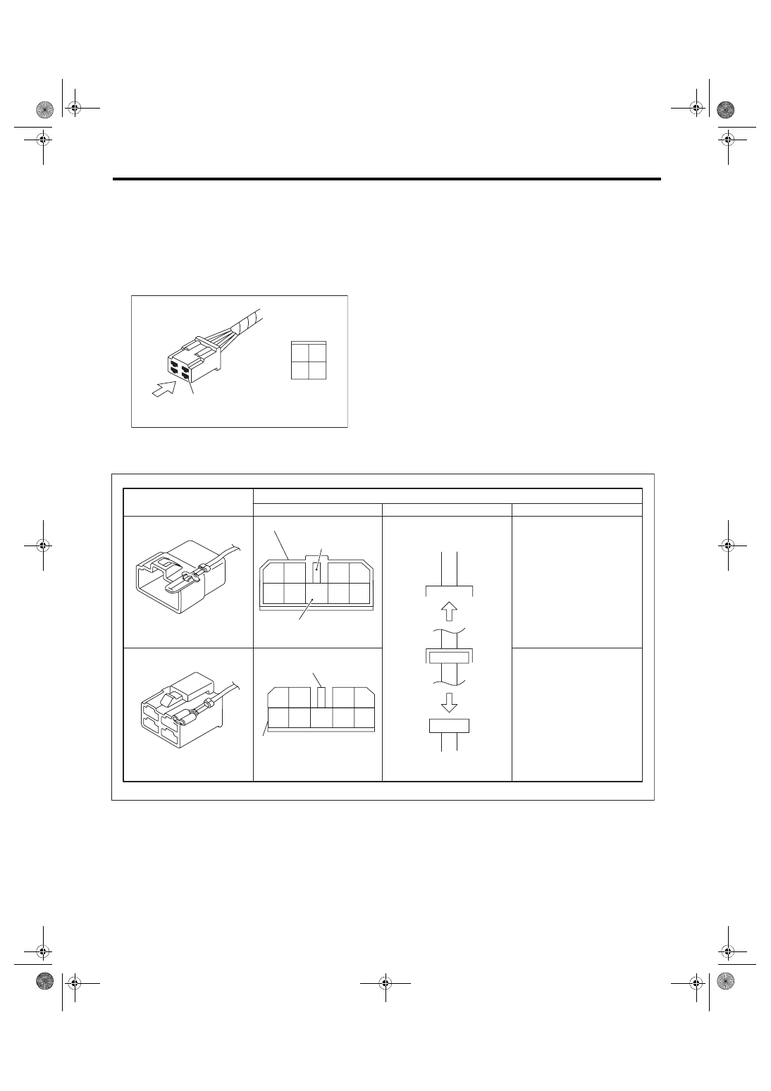
• Each connector and its terminal position are indicated by a sketch of the connector in a disconnected state
which is viewed from the front.
• The number of poles or pins, presence of a lock are indicated in the sketch of each connector. In the
sketch, the highest pole number refers to the number of poles which the connector has. For example, the
sketch of the connector shown in figure indicates the connector has 9 poles.
WI-02746
Viewed from this direction
4
2
4
1
3
Connector used in vehicle
Sketch
Symbol
Number of poles
Numbered in order from upper
right to lower left.
Numbered in order from upper
left to lower right.
Connector shown in wiring diagram
Double frames
Indicates a lock
is included.
Indicates the number of poles.
4
3
2
1
9
8
7
6
5
Indicates a lock is included.
Single frame
1
2
3
4
5
6
7
8
9
WI-02747