Subaru Impreza 3 / Impreza WRX / Impreza WRX STI. Manual - part 790
 

  Index      Subaru     Subaru Impreza 3 / Impreza WRX / Impreza WRX STI - service repair manual 2008-2014 year


Search            


Content   ..  788  789  790  791   ..


Subaru Impreza 3 / Impreza WRX / Impreza WRX STI. Manual - part 790


LAN(diag)-69

Diagnostic Procedure with Diagnostic Trouble Code (DTC)

LAN SYSTEM (DIAGNOSTICS)

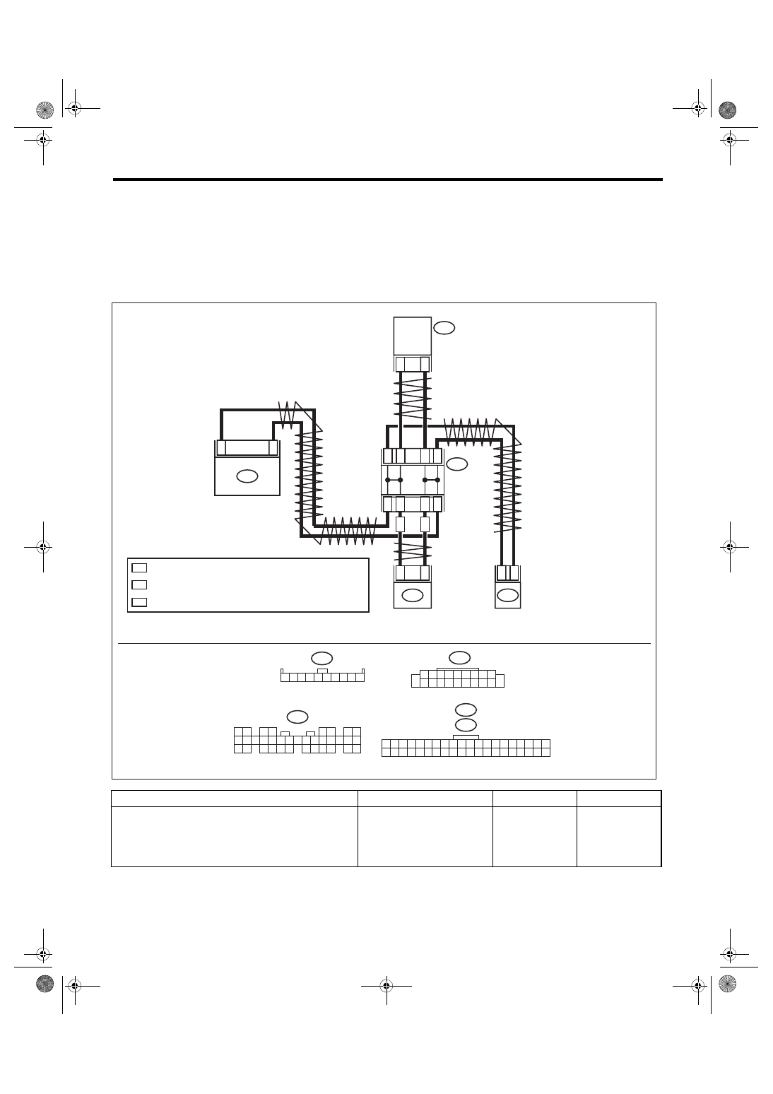
P: DTC U1302 CAN-LS BUS OFF

DTC DETECTING CONDITION:

Integrated unit communication is shut down because of low speed CAN error.

TROUBLE SYMPTOM:

Display error may occur in fuel gauge because the CAN communication is not transmitted (sending/receiv-

ing) normally.

WIRING DIAGRAM:

CAN communication system <Ref. to WI-171, WIRING DIAGRAM, CAN Communication System.>

Step

Check

Yes

No

1

CHECK DTC.
Read the DTC of body integrated unit using 
Subaru Select Monitor. <Ref. to LAN(diag)-13, 
READ DIAGNOSTIC TROUBLE CODE (DTC), 
OPERATION, Subaru Select Monitor.>

Is U1302 a current malfunc-
tion?

Go to step 

2.

Go to step 

8.

2

*

1

*

i84

1 2

3 4

5 6

7 8

9 10 11 12

14 15 16 17 18 19 20 21 22 23

24 25

26 27 28 29

30 31 32 33

34 35

13

i88

i10

1 2 3 4 5 6 7 8 9 10 11 12 13 14 15 16 17 18 19 20

21 22 23 24 25 26 27 28 29 30 31 32 33 34 35 36 37 38 39 40

i77

1 2 3 4 5 6 7 8 9 10

i85

1 2 3 4 5 6 7 8 9

10 11 12 13 14 15 16 17 18 19 20

2

*

2

*

2

*

2

*

1

*

1

*

1

*

1

*

11

12

AA

AA

AA

20

i85

i88

19

27

i10

26

i77

i84

1

9

LAN01360

BODY

 INTEGRATED 

UNIT

CAN JOINT

 CONNECT

OR

COMBINATION 

METER

AUDIO

: AUTO A/C

A/C

 CONTROL 

PANEL

: TERMINAL No. OPTIONAL ARRANGEMENT AMONG 1, 2, 3, 4 AND 5

: TERMINAL No. OPTIONAL ARRANGEMENT AMONG 6, 7, 8, 9 AND 10

LAN(diag)-70

Diagnostic Procedure with Diagnostic Trouble Code (DTC)

LAN SYSTEM (DIAGNOSTICS)

2

CHECK DTC.
1) Turn the ignition switch to OFF.
2) Disconnect all control module connectors 
(i84, i10, i88, i85) that are connected to low 
speed CAN communication line.
3) Connect the disconnected connectors.
4) Turn the ignition switch to ON.
5) Read the DTC of body integrated unit using 
Subaru Select Monitor.

Is U1302 a current malfunc-
tion?

Go to step 

3.

Go to step 

8.

3

CHECK HARNESS.
1) Turn the ignition switch to OFF.
2) Disconnect all control module connectors 
(i84, i10, i88, i85) that are connected to low 
speed CAN communication line.
3) Using the tester, check for open, short 
(power supply-output short, GND-output short) 
in the harness.

Connector & terminal

(i84) No. 1 — (i10) No. 27 (combination 
meter):
(i84) No. 9 — (i10) No. 26 (combination 
meter):
(i84) No. 1 — (i88) No. 20 (auto A/C):
(i84) No. 9 — (i88) No. 19 (auto A/C):
(i84) No. 1 — (i85) No. 12 (audio):
(i84) No. 9 — (i85) No. 11 (audio):

Is harness normal?

Go to step 

4.

Repair or replace 
the harness.

4

CHECK HARNESS.
1) Connect the disconnected connectors.
2) Using the tester, measure the resistance 
between harness connector and chassis 
ground.

Connector & terminal

(i84) No. 1 — Chassis ground:
(i84) No. 9 — Chassis ground:

Is the resistance 1 MΩ or 
more?

Go to step 

5.

Go to step 

7.

5

CHECK HARNESS.
1) Turn the ignition switch to ON.
2) Using the tester, measure the voltage 
between harness connector and chassis 
ground.

Connector & terminal

(i84) No. 1 (+) — Chassis ground (–):
(i84) No. 9 (+) — Chassis ground (–):

Is the voltage less than 6 V?

Replace the body 
integrated unit. 
<Ref. to SL-48, 
REMOVAL, Body 
Integrated Unit.>

Go to step 

6.

6

CHECK HARNESS.
With the tester connected, disconnect control 
module.

Is there any control module 
whose voltage has changed?

Replace the con-
trol module whose 
voltage has 
changed.

Repair or replace 
the short circuit of 
the harness.

7

CHECK HARNESS.
With the tester connected, disconnect control 
module.

Is there any control module 
whose resistance has 
changed?

Replace the con-
trol module whose 
resistance has 
changed.

Repair or replace 
the short circuit of 
the harness.

8

CHECK HARNESS.
1) Turn the ignition switch to OFF.
2) Shake the harness used for low speed CAN 
communication circuit.
3) Turn the ignition switch to ON.
4) Read the DTC of body integrated unit using 
Subaru Select Monitor.

Is U1302 a current malfunc-
tion?

Repair or replace 
the open, short cir-
cuit of the harness.

Go to step 

9.

Step

Check

Yes

No

LAN(diag)-71

Diagnostic Procedure with Diagnostic Trouble Code (DTC)

LAN SYSTEM (DIAGNOSTICS)

9

CHECK CONNECTOR.
1) Turn the ignition switch to OFF.
2) Disconnect all control module connectors 
(i84, i10, i88, i85) that are connected to low 
speed CAN communication line.

Is there poor contact of connec-
tor terminal?

Repair the connec-
tor terminal, or 
replace harness.

Temporary com-
munication failure 
occurs.

Step

Check

Yes

No

LAN(diag)-72

Diagnostic Procedure with Diagnostic Trouble Code (DTC)

LAN SYSTEM (DIAGNOSTICS)

Q: DTC U1311 CAN-LS METER UNIT DATA ABNORMAL

DTC DETECTING CONDITION:

Received error data from meter.

TROUBLE SYMPTOM:

Defective data from combination meter occurs.

WIRING DIAGRAM:

CAN communication system <Ref. to WI-171, WIRING DIAGRAM, CAN Communication System.>

Step

Check

Yes

No

1

CHECK DTC.
Read the DTC of body integrated unit using 
Subaru Select Monitor. <Ref. to LAN(diag)-13, 
READ DIAGNOSTIC TROUBLE CODE (DTC), 
OPERATION, Subaru Select Monitor.>

Is DTC U1300 or U1302 dis-
played?

Perform the diag-
nosis according to 
DTC.

Go to step 

2.

2

CHECK DTC.
Read the DTC of body integrated unit using 
Subaru Select Monitor.

Is U1311 a current malfunc-
tion?

Go to step 

3.

Go to step 

4.

3

CHECK DTC.
1) Turn the ignition switch to OFF.
2) Disconnect the combination meter connec-
tor (i10).
3) Connect the disconnected connectors.
4) Turn the ignition switch to ON.
5) Read the DTC of body integrated unit using 
Subaru Select Monitor.

Is U1311 a current malfunc-
tion?

Replace the com-
bination meter. 
<Ref. to IDI-16, 
REMOVAL, Com-
bination Meter.>

Go to step 

4.

4

CHECK HARNESS.
1) Turn the ignition switch to OFF.
2) Shake the harness used for low speed CAN 
communication circuit.
3) Turn the ignition switch to ON.
4) Read the DTC of body integrated unit using 
Subaru Select Monitor.

Is U1311 a current malfunc-
tion?

Repair or replace 
the harness.

Go to step 

5.

5

CHECK CONNECTOR.
1) Turn the ignition switch to OFF.
2) Disconnect all control module connectors 
(i84, i10, i88, i85) that are connected to low 
speed CAN communication line.

Is there poor contact of connec-
tor terminal?

Repair the connec-
tor terminal, or 
replace harness.

Temporary com-
munication failure 
occurs.

i10

26

27

i84

A9

A1

LAN00292

A:

A:

i84

1 2

3 4

5 6

7 8

9 10 11 12

14 15 16 17 18 19 20 21 22 23

24 25

26 27 28 29

30 31 32 33

34 35

13

i10

1 2 3 4 5 6 7 8 9 10 11 12 13 14 15 16 17 18 19 20

21 22 23 24 25 26 27 28 29 30 31 32 33 34 35 36 37 38 39 40

BODY INTEGRATED

UNIT

COMBINATION 

METER

TWISTED PAIR LINE


Content   ..  788  789  790  791   ..