Subaru Impreza 3 / Impreza WRX / Impreza WRX STI. Manual - part 786


  Index      Subaru     Subaru Impreza 3 / Impreza WRX / Impreza WRX STI - service repair manual 2008-2014 year


Search            


Content   ..  784  785  786  787   ..


Subaru Impreza 3 / Impreza WRX / Impreza WRX STI. Manual - part 786


LAN(diag)-53

Diagnostic Procedure with Diagnostic Trouble Code (DTC)

LAN SYSTEM (DIAGNOSTICS)

I: DTC U1213 CAN-HS VDC/ABS DATA ABNORMAL

DTC DETECTING CONDITION:

Received error data from VDC/ABS CM.

TROUBLE SYMPTOM:

It is possible that brake control error may occur.
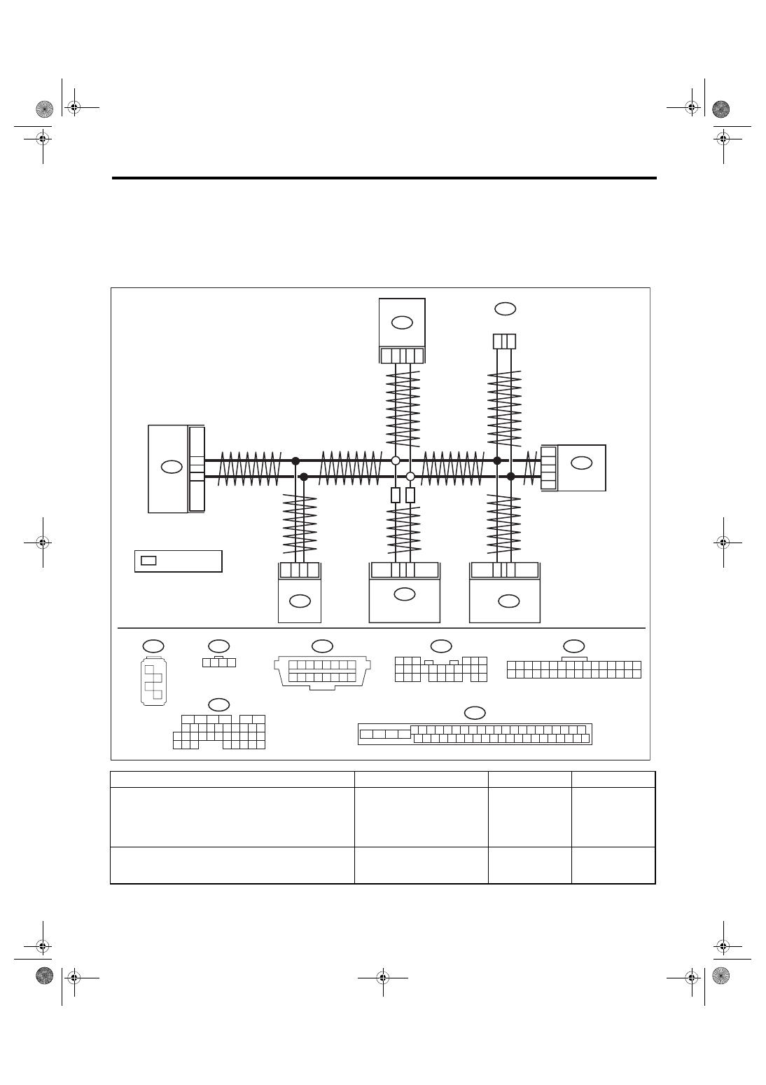
WIRING DIAGRAM:

CAN communication system <Ref. to WI-171, WIRING DIAGRAM, CAN Communication System.>

Step

Check

Yes

No

1

CHECK DTC.
Read all DTCs using the Subaru Select Monitor. 
<Ref. to LAN(diag)-13, READ DIAGNOSTIC 
TROUBLE CODE (DTC), OPERATION, Subaru 
Select Monitor.>

Is there DTC U1202?

Perform the diag-
nosis according to 
DTC.

Go to step 

2.

2

CHECK DTC.
Read the DTC of body integrated unit using 
Subaru Select Monitor.

Is U1213 a current malfunc-
tion?

Go to step 

3.

Go to step 

4.

2

1

B231

1

8

2

B380

B3

B9

B280

B:

6

14

B40

B380

1 2 3 4

17 18 19 20

5 6 7 8

21 22 23 24

9 10 11 12

25 26 27 28

13 14 15 16
29 30 31 32

4 5 6 7 8 9

6

2

7

2

8

2

9

2

0

3

2 3

1

1

3

2

3

3

3

4

3

5

3

6

3

0

1

1

1

4

1

5

1

6

1

7

1

8

1

9

1

7

3

8

3

9

3

0

4

2

1

3

1

1

4

2

4

3

4

4

4

5

4

6

4

0

2

1

2

3

2

4

2

2

2

5

2

B310

B231

1 2 3 4

B230

1

2

3

4

C: B136

16

10 11 12 13 14 15

25

24

30

9

8

7

17 18 19 20
28

21 22 23

29

32

31

1

2

3

4

5

6

27

26

33 34 35

B280

B:

1 2 3

4 5 6

7 8 9 10 11 12 13 14 15 16 17

18 19 20

21 22 23 24

25 26

1 2 3 4 5 6 7 8

9 10 11 12 13 14 15 16

B40

C17

C28

C: B136

B230

3

2

B310

10

35

LAN00907

SI

SI

SI

VDC CM

ECM

DCCD CM

YAW RATE &

 G SENSOR

: WITH SI-DRIVE

DATA LINK 

CONNECTOR

BODY 

INTEGRATED 

UNIT

STEERING

 ANGLE

 SENSOR

LAN(diag)-54

Diagnostic Procedure with Diagnostic Trouble Code (DTC)

LAN SYSTEM (DIAGNOSTICS)

3

CHECK DTC.
1) Turn the ignition switch to OFF.
2) Disconnect the VDC/ABS CM connector.
3) Connect the disconnected connectors.
4) Turn the ignition switch to ON.
5) Read the DTC of body integrated unit using 
Subaru Select Monitor.

Is U1213 a current malfunc-
tion?

Replace the VDC/
ABS CM. <Ref. to 
VDC-8, 
REMOVAL, VDC 
Control Module 
and Hydraulic Con-
trol Unit 
(VDCCM&H/U).>

Go to step 

4.

4

CHECK HARNESS.
1) Turn the ignition switch to OFF.
2) Shake the harness used for CAN communi-
cation circuit.
3) Turn the ignition switch to ON.
4) Read the DTC of body integrated unit using 
Subaru Select Monitor.

Is U1213 a current malfunc-
tion?

Repair or replace 
the harness.

Go to step 

5.

5

CHECK CONNECTOR.
1) Turn the ignition switch to OFF.
2) Disconnect the connector that is connected 
to high speed CAN circuit.

Is there poor contact of connec-
tor terminal?

Repair the connec-
tor terminal, or 
replace harness.

It is possible that 
temporary poor 
communication 
occurs.

Step

Check

Yes

No

LAN(diag)-55

Diagnostic Procedure with Diagnostic Trouble Code (DTC)

LAN SYSTEM (DIAGNOSTICS)

J: DTC U1216 HIGH-SPEED CAN (DCCD) DATA ERROR

DTC DETECTING CONDITION:

Received error data from DCCD CM.

TROUBLE SYMPTOM:

DCCD indicator blinks.

WIRING DIAGRAM:

CAN communication system <Ref. to WI-171, WIRING DIAGRAM, CAN Communication System.>

Step

Check

Yes

No

1

CHECK DTC.
Read all DTCs using the Subaru Select Monitor. 
<Ref. to LAN(diag)-13, READ DIAGNOSTIC 
TROUBLE CODE (DTC), OPERATION, Subaru 
Select Monitor.>

Is there DTC U1202?

Perform the diag-
nosis according to 
DTC.

Go to step 

2.

2

CHECK DTC.
Read the DTC of body integrated unit using 
Subaru Select Monitor.

Is U1216 a current malfunc-
tion?

Go to step 

3.

Go to step 

4.

2

1

B231

1

8

2

B380

B3

B9

B280

B:

6

14

B40

B380

1 2 3 4

17 18 19 20

5 6 7 8

21 22 23 24

9 10 11 12

25 26 27 28

13 14 15 16
29 30 31 32

4 5 6 7 8 9

6

2

7

2

8

2

9

2

0

3

2 3

1

1

3

2

3

3

3

4

3

5

3

6

3

0

1

1

1

4

1

5

1

6

1

7

1

8

1

9

1

7

3

8

3

9

3

0

4

2

1

3

1

1

4

2

4

3

4

4

4

5

4

6

4

0

2

1

2

3

2

4

2

2

2

5

2

B310

B231

1 2 3 4

B230

1

2

3

4

C: B136

16

10 11 12 13 14 15

25

24

30

9

8

7

17 18 19 20
28

21 22 23

29

32

31

1

2

3

4

5

6

27

26

33 34 35

B280

B:

1 2 3

4 5 6

7 8 9 10 11 12 13 14 15 16 17

18 19 20

21 22 23 24

25 26

1 2 3 4 5 6 7 8

9 10 11 12 13 14 15 16

B40

C17

C28

C: B136

B230

3

2

B310

10

35

LAN00907

SI

SI

SI

VDC CM

ECM

DCCD CM

YAW RATE &

 G SENSOR

: WITH SI-DRIVE

DATA LINK 

CONNECTOR

BODY 

INTEGRATED 

UNIT

STEERING

 ANGLE

 SENSOR

LAN(diag)-56

Diagnostic Procedure with Diagnostic Trouble Code (DTC)

LAN SYSTEM (DIAGNOSTICS)

3

CHECK DTC.
1) Turn the ignition switch to OFF.
2) Disconnect the DCCD CM connector.
3) Connect the disconnected connectors.
4) Turn the ignition switch to ON.
5) Read the DTC of body integrated unit using 
Subaru Select Monitor.

Is U1216 a current malfunc-
tion?

Replace the DCCD 
CM. <Ref. to 6MT-
123, REMOVAL, 
Driver’s Control 
Center Differential 
Control Module.>

Go to step 

4.

4

CHECK HARNESS.
1) Turn the ignition switch to OFF.
2) Shake the harness used for CAN communi-
cation circuit.
3) Turn the ignition switch to ON.
4) Read the DTC of body integrated unit using 
Subaru Select Monitor.

Is U1216 a current malfunc-
tion?

Repair or replace 
the harness.

Go to step 

5.

5

CHECK CONNECTOR.
1) Turn the ignition switch to OFF.
2) Disconnect the connector that is connected 
to high speed CAN circuit.

Is there poor contact of connec-
tor terminal?

Repair the connec-
tor terminal, or 
replace harness.

Temporary com-
munication failure 
occurs.

Step

Check

Yes

No


Content   ..  784  785  786  787   ..