Subaru Impreza 3 / Impreza WRX / Impreza WRX STI. Manual - part 763
CC(diag)-13
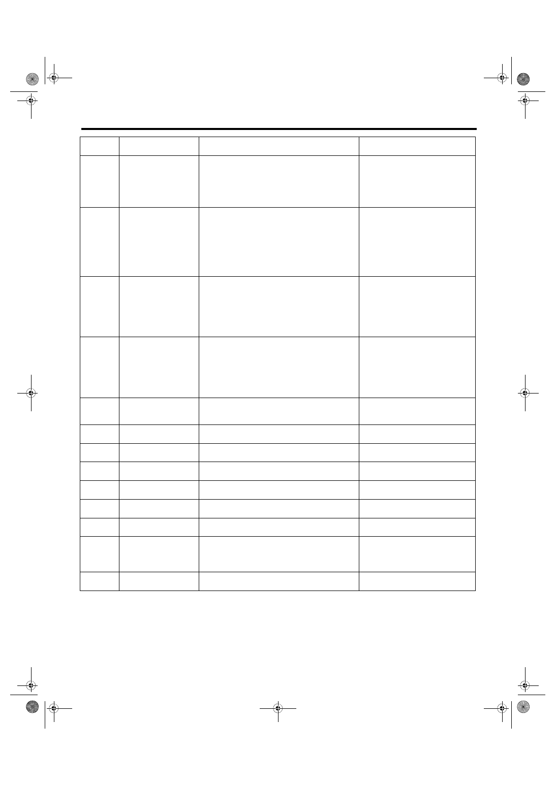
List of Cancel Code
CRUISE CONTROL SYSTEM (DIAGNOSTICS)
32
Cruse Control out of
Range
• Controlled vehicle speed decreased under the
limit during cruising.
• Set operation was performed at vehicle speed
unavailable for setting.
• RESUME operation was performed without
memorized vehicle speed.
34
Prohibition of cruise
control at continuing big
Accel. angle
The vehicle has been driven at higher speed than
set vehicle speed for an abnormally long time
(approximately 10 minutes) during cruise driving.
35
Prohibition of cruise
control at vehicle speed
F/B malfunction
Set vehicle speed cannot be kept because of some
reasons (steep uphill, parking brake, abnormal
decrease of engine output, etc.) during cruise driv-
ing.
41
VDC/TCS Operating
Vehicle dynamics control (VDC) or TCS is oper-
ated during cruise driving or cruise setting.
43
ABS/VDC Failure
ABS or Vehicle dynamics control (VDC) system
malfunction is detected during cruise driving or
cruise setting.
<Ref. to CC(diag)-24, 43, Diagnostic
Procedure with Cancel Code.>
44
Body Integrated unit
Failure
Body integrated unit system malfunction is
detected during cruise driving or cruise setting.
<Ref. to CC(diag)-24, 44, Diagnostic
Procedure with Cancel Code.>
45
Meter Failure
Combination meter malfunction is detected during
cruise driving or cruise setting.
<Ref. to CC(diag)-24, 45, Diagnostic
Procedure with Cancel Code.>
61
Brake switch abnormal
Malfunction in the stop light & brake switch is
detected.
<Ref. to CC(diag)-24, 61, Diagnostic
Procedure with Cancel Code.>
62
Neutral Switch Failure
Neutral position switch malfunction is detected.
<Ref. to CC(diag)-24, 62, Diagnostic
Procedure with Cancel Code.>
63
Abnormality of change
in vehicle speed
Malfunction of vehicle speed signal variation is
detected.
<Ref. to CC(diag)-25, 63, Diagnostic
Procedure with Cancel Code.>
64
Engine Sensor Failure 1 Malfunction related to engine is detected.
<Ref. to CC(diag)-25, 64, Diagnostic
Procedure with Cancel Code.>
65
Abnormality 1 of
switches related to
cruise control
Cruise control command switch malfunction is
detected. (When the switch is pressed ON for a
long time (approximately two minutes), stuck ON
condition is detected.)
<Ref. to CC(diag)-25, 65, Diagnostic
Procedure with Cancel Code.>
66
Cruise Control Calcula-
tion Error
Cruise control calculation (microcomputer) mal-
function is detected.
<Ref. to CC(diag)-25, 66, Diagnostic
Procedure with Cancel Code.>
Cancel
code
Item
Contents of diagnosis
Note