Subaru Impreza 3 / Impreza WRX / Impreza WRX STI. Manual - part 710
SE-9
Front Seat
SEATS
2) Refer to the disassembly procedures for the driv-
er’s seat.
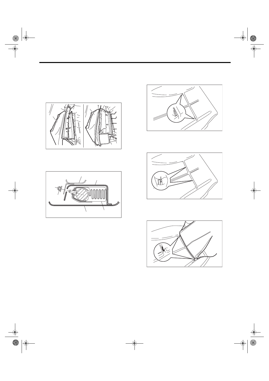
D: ASSEMBLY
CAUTION:
When installing the side airbag module assem-
bly, be sure to put the side airbag module be-
tween backrest cover and airbag guide cloth.
Besides, if the backrest cover is not installed
securely, the side airbag module may not be ac-
tivated properly, therefore keep strictly to the
following procedures.
• Be careful not to stain or damage the back-
rest cover during assembly.
• Do not reuse hog rings.
• Secure the hog ring using hog ring pliers.
• Install the hog rings to the specified points
securely and make sure that there is no wrinkle
or twisting on backrest cover.
1) Make sure that there is no foreign matter on side
airbag module.
2) Assemble the seat cover.
(1) Adjust so that the left and right clearances
between wire and seat pad become equal, and
mark the seat pad.
(2) Mark the center of the wire on the pad side
to which the hog ring is attached.
(3) Insert the wire into the seat cover, and align
the wire with the position marked in step 1).
(A) Airbag guide cloth
(B) Backrest cover
(C) Side airbag module ASSY
(1) Backrest frame ASSY
(2) Airbag guide cloth
(3) Backrest cover
(4) Side airbag module ASSY
(5) Hexagon cap nut
SE-00798
(B)
(B)
(B)
(B)
(B)
(B)
(C)
(A)
(A)
(A)
(A)
(A)
(A)
AB-01905
(2)
(1)
(5)
(4)
(3)
(1) Marking
(1) Marking
SE-01259
(1)
SE-01260
(1)
SE-01261