Subaru Impreza 3 / Impreza WRX / Impreza WRX STI. Manual - part 652
AB(diag)-147
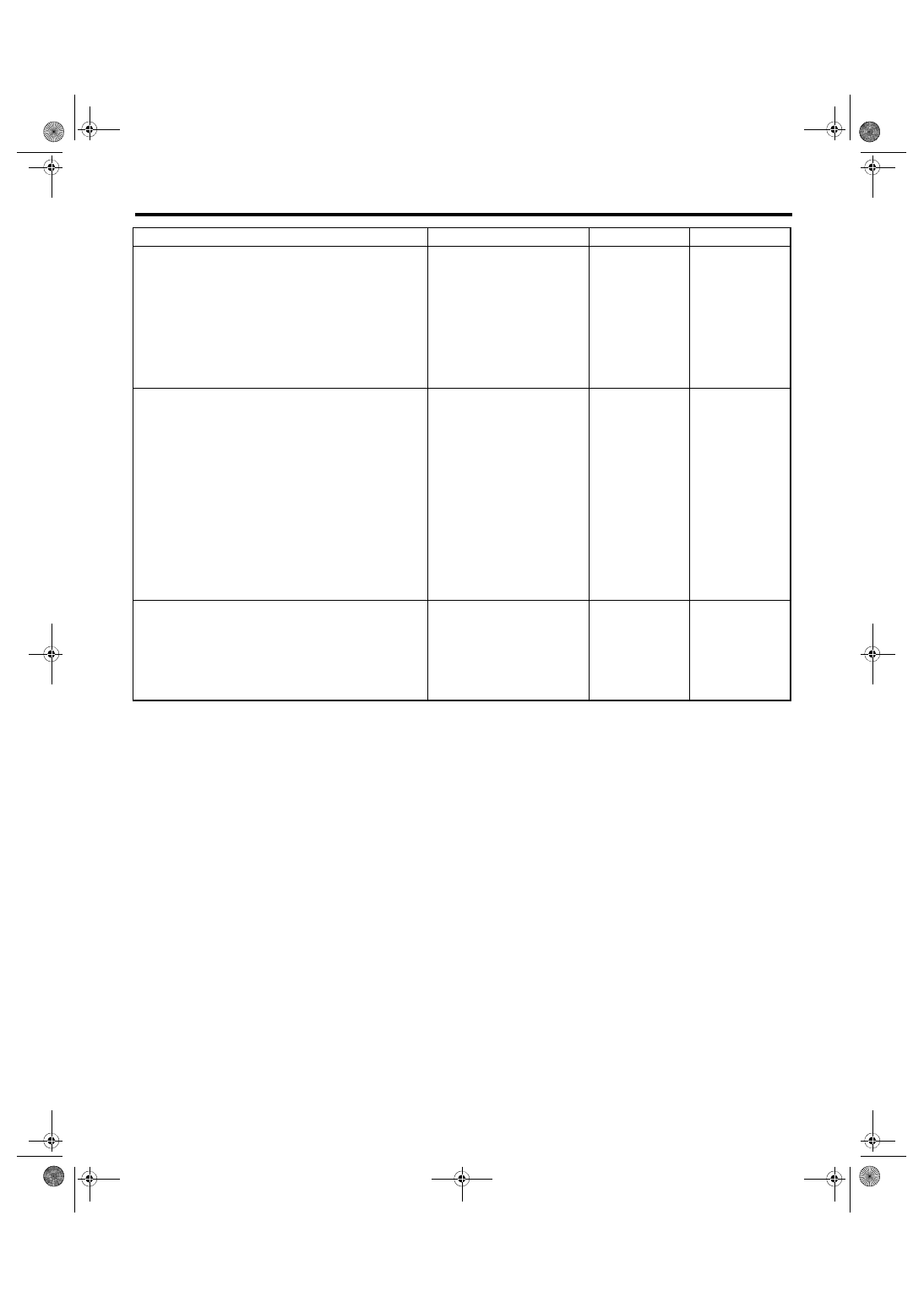
Diagnostic Chart with Trouble Code
AIRBAG SYSTEM (DIAGNOSTICS)
BP:DTC E3 FRONT SENSOR BUS RH COMMUNICATION ERROR
NOTE:
Refer to DTC A1 for DTC E3. <Ref. to AB(diag)-145, DTC A1 FRONT SENSOR BUS COMMUNICATION
ERROR, Diagnostic Chart with Trouble Code.>
BQ:DTC E4 FRONT SENSOR BUS RH COMMUNICATION ERROR
NOTE:
Refer to DTC A1 for DTC E4. <Ref. to AB(diag)-145, DTC A1 FRONT SENSOR BUS COMMUNICATION
ERROR, Diagnostic Chart with Trouble Code.>
5
CHECK AIRBAG MAIN HARNESS (FRONT
SENSOR BUS RH).
Measure the resistance between connector
(4AG) in the test harness AG and chassis
ground, and the resistance between connector
(4AG) terminals in the test harness AG.
Connector & terminal
(4AG) No. 12 — Chassis ground:
(4AG) No. 14 — Chassis ground:
(4AG) No. 12 — (4AG) No. 14:
Is the resistance 1 MΩ or
more?
Replace the airbag
main harness
along with body
harness.
6
CHECK AIRBAG CONTROL MODULE.
1) Connect all connectors.
2) Clear the memory.
3) Perform the Inspection Mode.
4) Read the DTC.
Is the same DTC displayed?
7
CHECK FOR ANY OTHER DTC ON DISPLAY. Is any other DTC displayed?
Finish the diagno-
sis.
Step
Check
Yes
No