Subaru Impreza 3 / Impreza WRX / Impreza WRX STI. Manual - part 606


  Index      Subaru     Subaru Impreza 3 / Impreza WRX / Impreza WRX STI - service repair manual 2008-2014 year


Search            


Content   ..  604  605  606  607   ..


Subaru Impreza 3 / Impreza WRX / Impreza WRX STI. Manual - part 606


AC(diag)-29

Diagnostic Procedure for Sensors

HVAC SYSTEM (AUTO A/C) (DIAGNOSTICS)

8. Diagnostic Procedure for Sensors
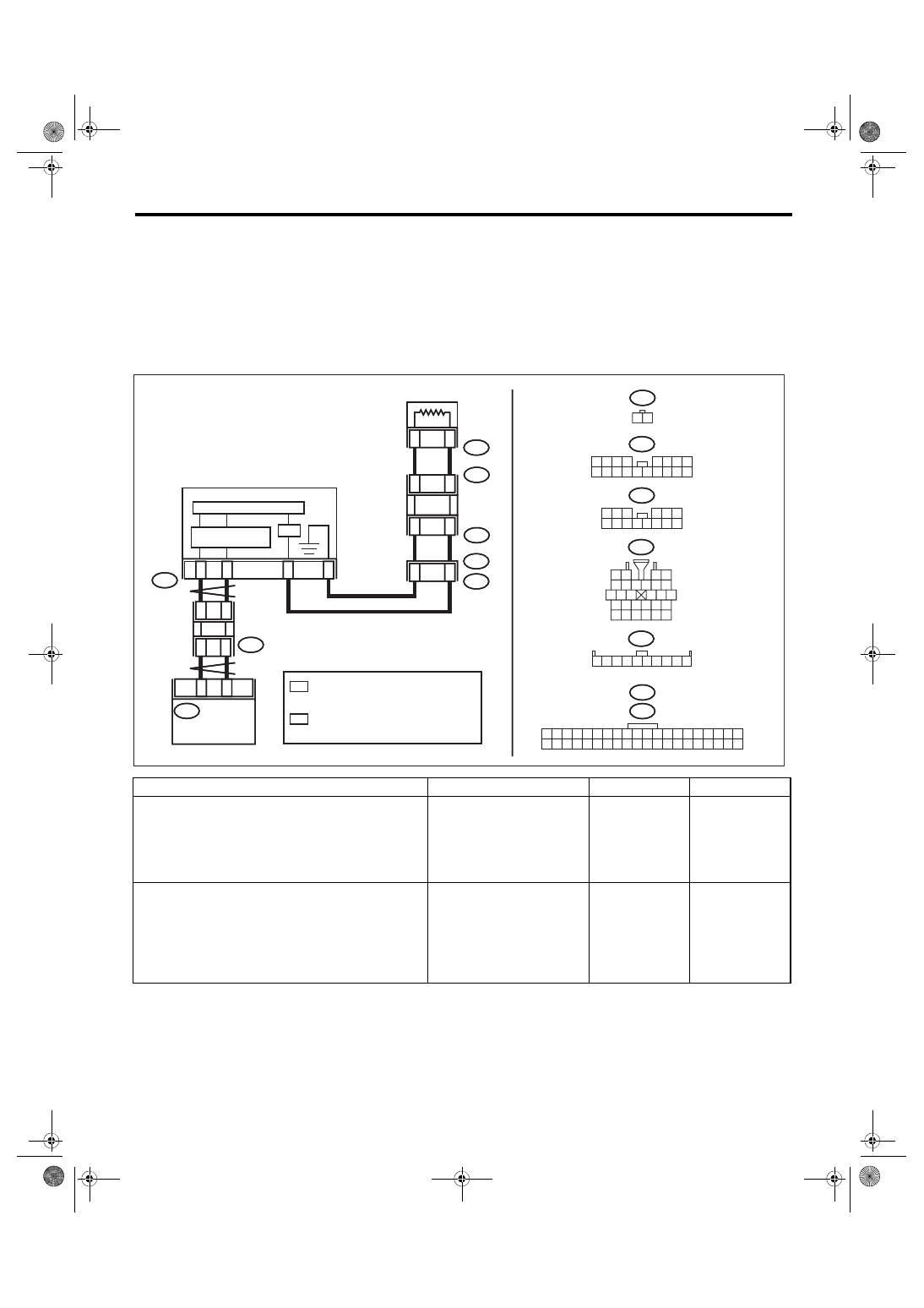
A: AMBIENT SENSOR

TROUBLE SYMPTOM:

• Fan speed is not switched when the fan dial is in AUTO position.

• Failure related to the ambient sensor is indicated in self-diagnosis.

WIRING DIAGRAM:

Air conditioning system, auto A/C model <Ref. to WI-77, AUTO A/C MODEL, WIRING DIAGRAM, Air Con-

ditioning System.>

Step

Check

Yes

No

1

CHECK AMBIENT SENSOR.
Perform the inspection of ambient sensor unit. 
<Ref. to AC-45, INSPECTION, Ambient Sensor 
(Auto A/C Model).>

Is the ambient sensor operating 
properly?

Go to step 

2.

Replace the ambi-
ent sensor. <Ref. 
to AC-44, 
REMOVAL, Ambi-
ent Sensor (Auto 
A/C Model).>

2

CHECK INPUT SIGNAL FOR AMBIENT SEN-
SOR.
1) Turn the ignition to ON.
2) Measure the voltage between connector 
(F78) terminals.

Connector & terminal

(F78) No. 2 (+) — No. 1 (–):

Is the voltage approx. 5 V?

Go to step 

6.

Go to step 

3.

I/F

*

1

*

2

B361

B361

1
7

2 3

4 5 6

8 9 10 11 12 13 14

i77

1 2 3 4 5 6 7 8 9 10

i3

5 6 7 8

2

1

9

4

3

10

24

22

23

25

27

26

28

11 12 13

14 15 16

17 18 19 20 21

F108

1
9

2 3

8

10

4

11 12 13 14 15 16

5 6 7

17 18

i77

*

1

*

2

*

1

*

2

1 2 3 4 5 6 7 8 9 10 11 12 13 14 15 16 17 18 19 20

21 22 23 24 25 26 27 28 29 30 31 32 33 34 35 36 37 38 39 40

i10

i88

2

1

i3

B38

i10

24

27

23

26

1 2

F78

2

1

F78

14

13

10

11

F108

B361

20

19

i88

AC-02343

AUTO A/C 

CONTROL 

MODULE

JOINT 

CONNECTOR

AMBIENT

 SENSOR

COMBINATION METER

MICRO COMPUTER

CAN TRANSCEIVER

 & RECEIVER

CAN JOINT 

CONNECTOR

: TERMINAL No. OPTIONAL ARRANGEMENT

 AMONG 6, 7, 8, 9 AND 10

: TERMINAL No. OPTIONAL ARRANGEMENT

 AMONG 1, 2, 3, 4 AND 5

AC(diag)-30

Diagnostic Procedure for Sensors

HVAC SYSTEM (AUTO A/C) (DIAGNOSTICS)

3

CHECK COMBINATION METER OUTPUT 
SIGNAL.
1) Turn the ignition switch to OFF.
2) Pull out the combination meter.
3) Disconnect the connector from ambient 
sensor.
4) Turn the ignition switch to ON.
5) Measure the voltage between the combina-
tion meter connector terminals.

Connector & terminal

(i10) No. 24 (+) — No. 23 (–):

Is the voltage approx. 5 V?

Go to step 

4.

Replace the com-
bination meter. 
<Ref. to IDI-16, 
REMOVAL, Com-
bination Meter.>

4

CHECK HARNESS CONNECTOR BETWEEN 
COMBINATION METER AND AMBIENT SEN-
SOR.
1) Turn the ignition switch to OFF.
2) Disconnect the connector from the combi-
nation meter.
3) Measure the resistance of harness between 
combination meter and ambient sensor.

Connector & terminal

(F78) No. 2 — (i10) No. 24:

Is the resistance less than 1 Ω? Go to step 

5.

Repair the open 
circuit of the har-
ness between the 
combination meter 
and ambient sen-
sor.

5

CHECK HARNESS CONNECTOR BETWEEN 
COMBINATION METER AND AMBIENT SEN-
SOR.
Measure the resistance of harness between 
combination meter and ambient sensor.

Connector & terminal

(F78) No. 1 — (i10) No. 23:

Is the resistance less than 1 Ω? Replace the com-

bination meter. 
<Ref. to IDI-16, 
REMOVAL, Com-
bination Meter.>

Repair the open 
circuit of the har-
ness between the 
combination meter 
and ambient sen-
sor.

6

CHECK HARNESS CONNECTOR BETWEEN 
COMBINATION METER AND AUTO A/C 
CONTROL MODULE.
1) Turn the ignition switch to OFF.
2) Disconnect the connector from the combi-
nation meter.
3) Disconnect the auto A/C control module 
connector.
4) Measure the resistance of harness between 
the combination meter and auto A/C control 
module.

Connector & terminal

(i88) No. 19 — (i10) No. 26:

Is the resistance less than 1 Ω? Go to step 

7.

Repair the open 
circuit in the har-
ness between the 
combination meter 
and auto A/C con-
trol module. <Ref. 
to LAN(diag)-6, 
LAN SYSTEM, 
CAUTION, Gen-
eral Description.>

7

CHECK HARNESS CONNECTOR BETWEEN 
COMBINATION METER AND AUTO A/C 
CONTROL MODULE.
Measure the resistance of harness between the 
combination meter and auto A/C control mod-
ule.

Connector & terminal

(i88) No. 20 — (i10) No. 27:

Is the resistance less than 1 Ω? Go to step 

8.

Repair the open 
circuit in the har-
ness between the 
combination meter 
and auto A/C con-
trol module. <Ref. 
to LAN(diag)-6, 
LAN SYSTEM, 
CAUTION, Gen-
eral Description.>

8

CHECK FOR POOR CONTACT.
Check poor contact of auto A/C control module 
connector.

Is there poor contact of connec-
tor?

Repair the connec-
tor.

Replace the auto 
A/C control mod-
ule. <Ref. to AC-
31, REMOVAL, 
Control Unit (Auto 
A/C Model).>

Step

Check

Yes

No

AC(diag)-31

Diagnostic Procedure for Sensors

HVAC SYSTEM (AUTO A/C) (DIAGNOSTICS)

B: IN-VEHICLE SENSOR

TROUBLE SYMPTOM:

• Blower fan speed, air flow outlet and FRESH/RECIRC do not change after turning the AUTO switch to ON.

• Failure related to the in-vehicle sensor is indicated in self-diagnosis.

WIRING DIAGRAM:

Air conditioning system, auto A/C model <Ref. to WI-77, AUTO A/C MODEL, WIRING DIAGRAM, Air Con-

ditioning System.>

Step

Check

Yes

No

1

CHECK IN-VEHICLE SENSOR.
Perform the inspection of in-vehicle sensor unit. 
<Ref. to AC-48, INSPECTION, In-Vehicle Sen-
sor (Auto A/C Model).>

Is the in-vehicle sensor nor-
mal?

Go to step 

2.

Replace the in-
vehicle sensor. 
<Ref. to AC-47, 
REMOVAL, In-
Vehicle Sensor 
(Auto A/C Model).>

2

CHECK INPUT SIGNAL FOR IN-VEHICLE 
SENSOR.
1) Turn the ignition switch to ON.
2) Measure the voltage between in-vehicle 
sensor harness connector terminals.

Connector & terminal

(i55) No. 2 (+) — No. 1 (–):

Is the voltage approx. 5 V?

Go to step 

6.

Go to step 

3.

3

CHECK AUTO A/C CONTROL MODULE 
OUTPUT SIGNAL.
1) Turn the ignition switch to OFF.
2) Remove the auto A/C control module.
3) Turn the ignition switch to ON.
4) Measure the voltage between connector 
terminals of auto A/C control module.

Connector & terminal

(i88) No. 17 (+) — (i88) No. 14 (–):

Is the voltage approx. 5 V?

Go to step 

4.

Go to step 

6.

AC-01700

i88

17

14

i55

1

2

i55

1 2

i88

1 2 3 4 5 6 7 8 9 10 11 12 13 14 15 16 17 18 19 20

21 22 23 24 25 26 27 28 29 30 31 32 33 34 35 36 37 38 39 40

AUTO A/C 

CONTROL 

MODULE

IN-VEHICLE

SENSOR

AC(diag)-32

Diagnostic Procedure for Sensors

HVAC SYSTEM (AUTO A/C) (DIAGNOSTICS)

4

CHECK HARNESS BETWEEN AUTO A/C 
CONTROL MODULE AND IN-VEHICLE SEN-
SOR.
1) Turn the ignition switch to OFF.
2) Disconnect the connector from the auto A/C 
control module.
3) Measure the resistance of harness between 
auto A/C control module and in-vehicle sensor.

Connector & terminal

(i55) No. 2 — (i88) No. 17:

Is the resistance less than 1 Ω? Go to step 

5.

Repair the harness 
between auto A/C 
control module and 
in-vehicle sensor.

5

CHECK HARNESS BETWEEN AUTO A/C 
CONTROL MODULE AND IN-VEHICLE SEN-
SOR.
Measure the resistance of harness between 
auto A/C control module and in-vehicle sensor.

Connector & terminal

(i55) No. 1 — (i88) No. 14:

Is the resistance less than 1 Ω? Go to step 

6.

Repair the harness 
between auto A/C 
control module and 
in-vehicle sensor.

6

CHECK FOR POOR CONTACT.
Check poor contact of auto A/C control module 
connector.

Is there poor contact of connec-
tor?

Repair the connec-
tor.

Replace the auto 
A/C control mod-
ule. <Ref. to AC-
31, REMOVAL, 
Control Unit (Auto 
A/C Model).>

Step

Check

Yes

No


Content   ..  604  605  606  607   ..