Subaru Impreza 3 / Impreza WRX / Impreza WRX STI. Manual - part 595


  Index      Subaru     Subaru Impreza 3 / Impreza WRX / Impreza WRX STI - service repair manual 2008-2014 year


Search            


Content   ..  593  594  595  596   ..


Subaru Impreza 3 / Impreza WRX / Impreza WRX STI. Manual - part 595


AC-39

Evaporator

HVAC SYSTEM (HEATER, VENTILATOR AND A/C)

B: INSTALLATION

CAUTION:

• Make sure that the water seal packing on the cover attachment area is securely attached.

• If the evaporator has been replaced, add an appropriate amount of compressor oil to the compres-

sor. <Ref. to AC-24, ADJUSTMENT, Compressor Oil.>

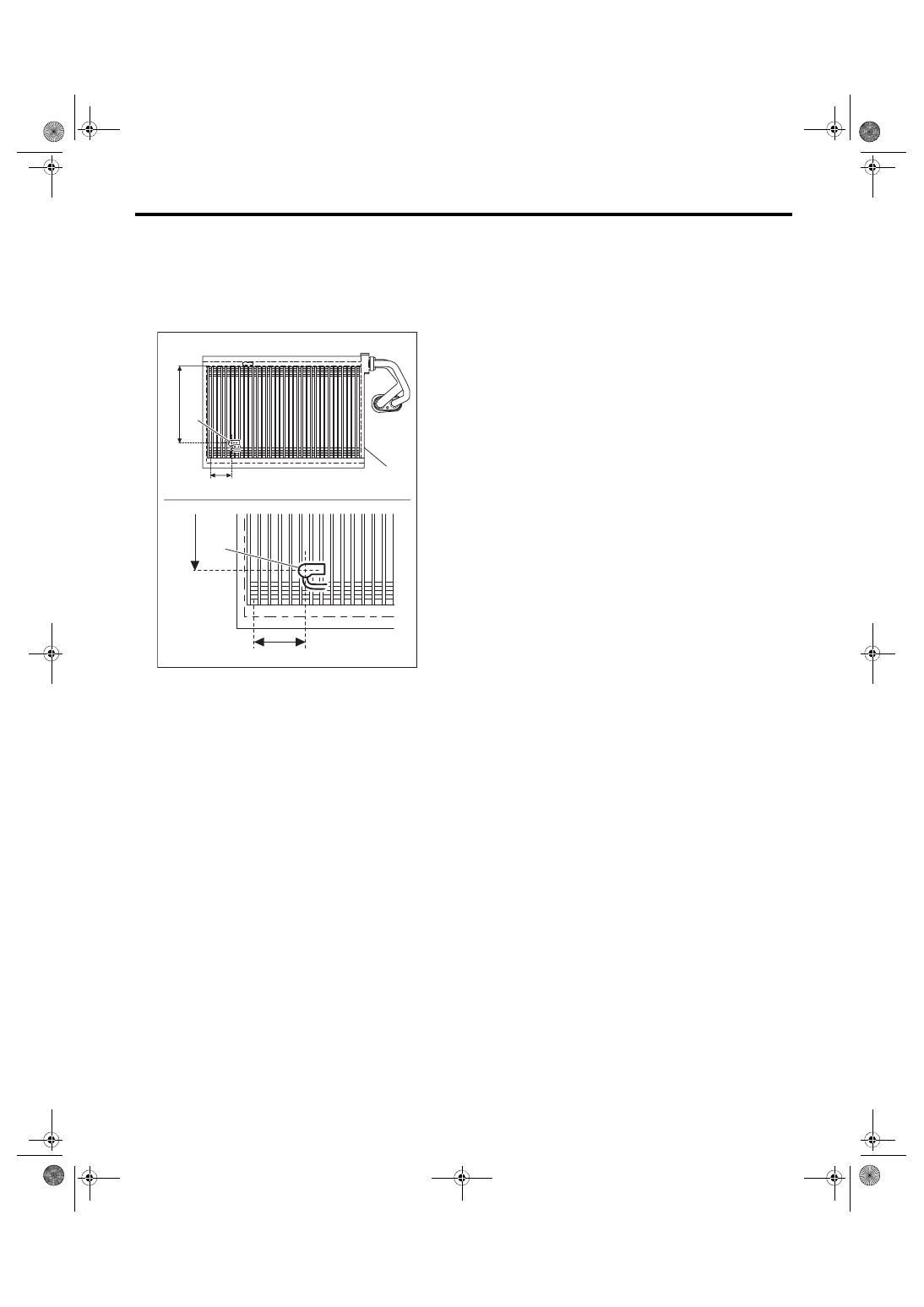
• Install the sensor in the location shown in the figures below.

1) Install each part in the reverse order of removal.

2) Charge refrigerant. <Ref. to AC-20, PROCEDURE, Refrigerant Charging Procedure.>
Tightening torque:

Refer to “COMPONENT” of “General Description”.

• Heater cooling unit: <Ref. to AC-4, HEATER COOLING UNIT, COMPONENT, General Description.>
• Blower motor unit: <Ref. to AC-6, BLOWER MOTOR UNIT, COMPONENT, General Description.>

(1) 148 mm (5.83 in) from the upper end of the fins
(2) Sixth row fin from the left end
(3) Sensor
(4) Evaporator

AC-01807

(3)

(2)

(1)

(3)

(2)

(1)

(4)

AC-40

Evaporator

HVAC SYSTEM (HEATER, VENTILATOR AND A/C)

C: INSPECTION

1. EVAPORATOR

1) Check the evaporator fin for dust. Blow with compressed air or flush fins with water as needed.

2) If any oil leak is found from the evaporator, replace the evaporator.

2. EVAPORATOR SENSOR

UNIT INSPECTION
Preparation tool: Circuit tester

1) Check the resistance between evaporator sensor terminals.

2) Replace the evaporator sensor if the inspection result is not within the standard value.

Terminal No.

Inspection conditions

Standard

1 — 2

-20°C

15.37 — 16.62 kΩ

-15°C

12.09 — 12.87 kΩ

-10°C

9.576 — 10.05 kΩ

-5°C

7.636 — 7.899 kΩ

0°C

6.132 — 6.256 kΩ

5°C

4.891 — 5.057 kΩ

10°C

3.928 — 4.113 kΩ

15°C

3.174 — 3.366 kΩ

20°C

2.581 — 2.77 kΩ

25°C

2.111 — 2.292 kΩ

30°C

1.737 — 1.907 kΩ

35°C

1.437 — 1.595 kΩ

40°C

1.195 — 1.34 kΩ

(122)

(104)

(86)

(68)

(50)

(32)

(14)

0

10

20

30

40

50

2 1

AC-02815

18.00

16.00

14.00

12.00

10.00

8.00

6.00

4.00

2.00

0.00

-30

-20

-10

(-32)

(-4)

: STANDARD (MIN TOLERANCE)

: STANDARD (MAX TOLERANCE)

RESIST

ANCE 

VALUE

TEMPERATURE

AC-41

Hose and Pipe

HVAC SYSTEM (HEATER, VENTILATOR AND A/C)

19.Hose and Pipe

A: REMOVAL

CAUTION:

• When disconnecting hoses, do not apply ex-

cessive force.

• Seal the disconnected hose, pipe and engag-

ing part of component with a plug or vinyl tape

to prevent foreign matter from entering.

1) Disconnect the ground cable from battery.

2) Using  the  refrigerant  recovery  system,  dis-

charge refrigerant. <Ref. to AC-19, PROCEDURE,

Refrigerant Recovery Procedure.>

3) Remove  the  bolt  and  detach  the  hoses  and

pipes.

B: INSTALLATION

CAUTION:

• Replace the O-rings with new parts.

• When connecting hoses, do not apply an ex-

cessive  force  to  them.  After  installing,  check

that no torsion or excessive tension applied to

the hoses.

• If the hose and pipe has been replaced, add

an appropriate amount of compressor oil to the

compressor.  <Ref.  to  AC-24,  ADJUSTMENT,

Compressor Oil.>

1) Install each part in the reverse order of removal.

2) Charge  refrigerant.  <Ref.  to  AC-20,  PROCE-

DURE, Refrigerant Charging Procedure.>
Tightening torque:

Refer to “COMPONENT” of “General Descrip-

tion”. <Ref. to AC-9, AIR CONDITIONING 

UNIT, COMPONENT, General Description.>

C: INSPECTION

Check  the  hoses  for  cracks,  damage  and  expan-

sion, and then replace it with a new part if defective.

AC-42

Relay and Fuse

HVAC SYSTEM (HEATER, VENTILATOR AND A/C)

20.Relay and Fuse

A: LOCATION

B: INSPECTION

1. FUSE

1) Remove the fuse and inspect visually.

2) If the fuse is blown out, replace the fuse.

2. RELAY

1) Connect  terminal  No.  4  to  the  battery  positive

terminal and the terminal No. 3 to the battery neg-

ative terminal, and check the resistance value be-

tween the relay terminals.

2) Replace the relay if the inspection result is not

within the standard value.

(1) Joint box
(2) Main fuse box

Main fan relay 1

(A)

Main fan relay 2

(B)

Sub fan relay

(C)

A/C relay

(D)

A/C Fuse

(E)

(E)

(1)

(2)

(A)

(D)

(C)

(B)

AC-01570

Continuity

Terminal No.

Specification

Yes

1 and 2

Less than 1 Ω

None

1 MΩ or more

LI-00001

(1)

(2)

(1)

(4)

(2)

(3)

(3)

(4)

SL-01317

(1)

(2)

(1)

(4)

(2)

(3)

(3)

(4)


Content   ..  593  594  595  596   ..