Subaru Impreza 3 / Impreza WRX / Impreza WRX STI. Manual - part 592
AC-27
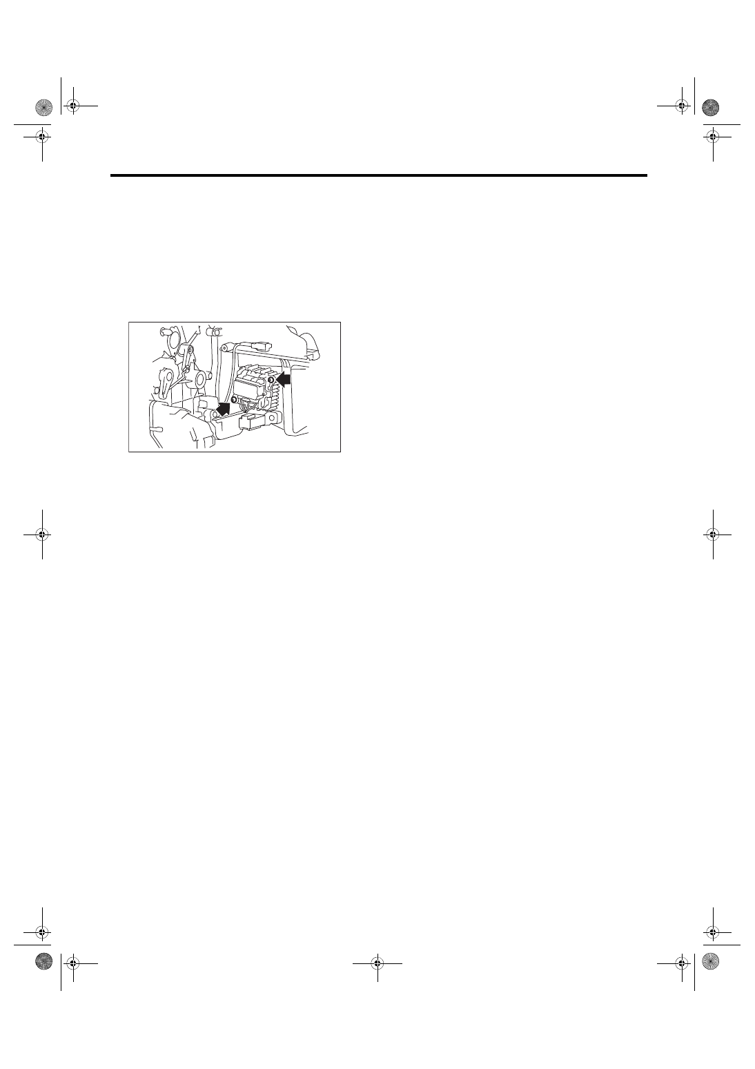
Power Transistor (Auto A/C Model)
HVAC SYSTEM (HEATER, VENTILATOR AND A/C)
10.Power Transistor (Auto A/C
Model)
A: REMOVAL
1) Remove the instrument panel lower. <Ref. to EI-
54, INSTRUMENT PANEL LOWER, REMOVAL,
2) Disconnect the power transistor connector.
3) Remove the screws and remove the power tran-
sistor.
B: INSTALLATION
Install each part in the reverse order of removal.
AC-01806