Subaru Impreza 3 / Impreza WRX / Impreza WRX STI. Manual - part 591


  Index      Subaru     Subaru Impreza 3 / Impreza WRX / Impreza WRX STI - service repair manual 2008-2014 year


Search            


Content   ..  589  590  591  592   ..


Subaru Impreza 3 / Impreza WRX / Impreza WRX STI. Manual - part 591


AC-23

Refrigerant Leak Check

HVAC SYSTEM (HEATER, VENTILATOR AND A/C)

6. Refrigerant Leak Check

A: INSPECTION

1) Operate the A/C system for approx. 10 minutes,

and  check  that  the  high-pressure  side  shows  at

least  690  kPa  (7.03  kgf/cm

2

, 100 psi). Then stop

the engine to start the leak test.

2) Starting from the connection between high-pres-

sure  pipe  and  evaporator,  check  the  system  for

leaks  along  the  high-pressure  side  through  the

compressor. The following items must be checked

thoroughly.

• Check  the  joint  and  seam  between  pressure

switch  (triple  pressure  switch)  and  high-pressure

pipe.

• Check the connections between condenser and

pipes, and welded joints on the condenser.
NOTE:

The leak tester may detect the oil on the condenser

fins as a leak.

• Check the joint between compressor and hoses.

• Check the machined area of the compressor and

other joints on the compressor.

• Check  the  compressor  shaft  seal  at  the  area

near the center of compressor clutch pulley.
NOTE:

Some shaft seals will show a slight amount of leak-

age, about 3 g (0.1 oz) per year. This is not a prob-

lem.

3) Starting from the connection between low-pres-

sure  pipe  and  evaporator,  check  the  system  for

leakage  along  the  low-pressure  side  through  the

compressor. The following items must be checked

thoroughly.

• Connection between 2 parts

• Connection between pipe and plate

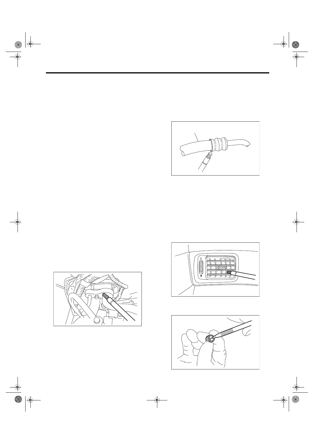
4) Visually  check  the  rubber  area  of  the  flexible

hose for cracks. Check the entire length of the flex-

ible hose, especially the connection with the metal

hose end.
CAUTION:

Carefully  check  the  external  surface  of  hoses

and pipes at approx. 25 mm (0.98 in) per sec-

ond.

5) Disconnect the drain hose from the heater case,

and check the hose end for at least 10 seconds.

After the test is finished, reconnect the drain hose.

6) Turn the ignition switch to the ON, and run the

blower at high speed for approx. 1 minute. Stop the

blower to check the ventilation grille on the instru-

ment panel. While moving the tester closer to the

grille, run the blower for 1 or 2 seconds, then stop it.

Check the grille at that position for at least 10 sec-

onds.

7) Check the valve in the service port.

8) Visually check the rubber seal in the service port

cap.

AC-00035

(A) Flexible hose

AC-00036

(A)

AC-01885

AC-00038

AC-24

Compressor Oil

HVAC SYSTEM (HEATER, VENTILATOR AND A/C)

7. Compressor Oil

A: PROCEDURE

NOTE:

Before making repairs, perform the oil return oper-

ation to return the compressor oil in circulation with

the refrigerant to the compressor.

1) Increase the engine to 1,500 rpm.

2) Turn the A/C switch to ON.

3) Turn the temperature control dial to MAX COOL

position.

4) Turn the FRESH/RECIRC switch to RECIRC po-

sition.

5) Turn the fan speed control dial to HI (MAX) posi-

tion.

6) Leave in this condition for 10 minutes.

B: ADJUSTMENT

• If a component has been replaced, add an ap-

propriate  amount  of  compressor  oil  (same  as  the

amount of remaining oil in removed component).

• When replacing the compressor, the new com-

pressor will already have the specified amount of

oil in it. Adjust the oil amount (so that the amount

remains the same as that of the removed compres-

sor) and install the new compressor.
NOTE:

Since the hygroscopicity of compressor oil is high,

perform this series of works quickly.

AC-25

Blower Motor Unit Assembly

HVAC SYSTEM (HEATER, VENTILATOR AND A/C)

8. Blower Motor Unit Assembly

A: REMOVAL

1) Disconnect the ground cable from battery.

2) Remove the instrument panel lower. <Ref. to EI-

54,  INSTRUMENT  PANEL  LOWER,  REMOVAL,

Center Console.>

3) Remove the engine ECM protect cover.

4) Disconnect the intake door actuator and blower

motor harness connectors.

5) Remove the relay holder.

6) Remove  the  bolts  and  nuts  to  remove  blower

motor unit assembly.

B: INSTALLATION

Install each part in the reverse order of removal.
Tightening torque:

Refer to “COMPONENT” of “General Descrip-

tion”. <Ref. to AC-6, BLOWER MOTOR UNIT, 

COMPONENT, General Description.>

AC-01772

AC-01773

AC-26

Blower Motor

HVAC SYSTEM (HEATER, VENTILATOR AND A/C)

9. Blower Motor

A: REMOVAL

1) Disconnect the ground cable from battery.

2) Disconnect the blower motor connector.

3) Turn over the floor mat near the blower motor.

4) Remove the screws and detach the blower mo-

tor.

B: INSTALLATION

Install each part in the reverse order of removal.

C: INSPECTION

1) Disconnect the blower motor connector.

2) Connect the battery positive (+) terminal to ter-

minal No. 2 of blower motor connector, and nega-

tive (–) terminal to terminal No. 1. Check that the

blower motor rotates normally.

3) If the blower motor does not operate normally,

replace the blower motor.

AC-01804

AC-01805

1

2


Content   ..  589  590  591  592   ..