Subaru Impreza 3 / Impreza WRX / Impreza WRX STI. Manual - part 517


  Index      Subaru     Subaru Impreza 3 / Impreza WRX / Impreza WRX STI - service repair manual 2008-2014 year


Search            


Content   ..  515  516  517  518   ..


Subaru Impreza 3 / Impreza WRX / Impreza WRX STI. Manual - part 517


DS-41

Rear Drive Shaft

DRIVE SHAFT SYSTEM

2. EXCEPT FOR STI MODEL

CAUTION:

Wrap shaft splines with vinyl tape to protect the

boot from scratches.
NOTE:

Use specified grease.
EBJ side:

NKG814

DOJ side:

NKG814

1) Install the EBJ boot to the specified position, and

fill it with 50 to 60 g (1.76 to 2.12 oz) of specified

grease.

2) Place the DOJ boot at the center of shaft.

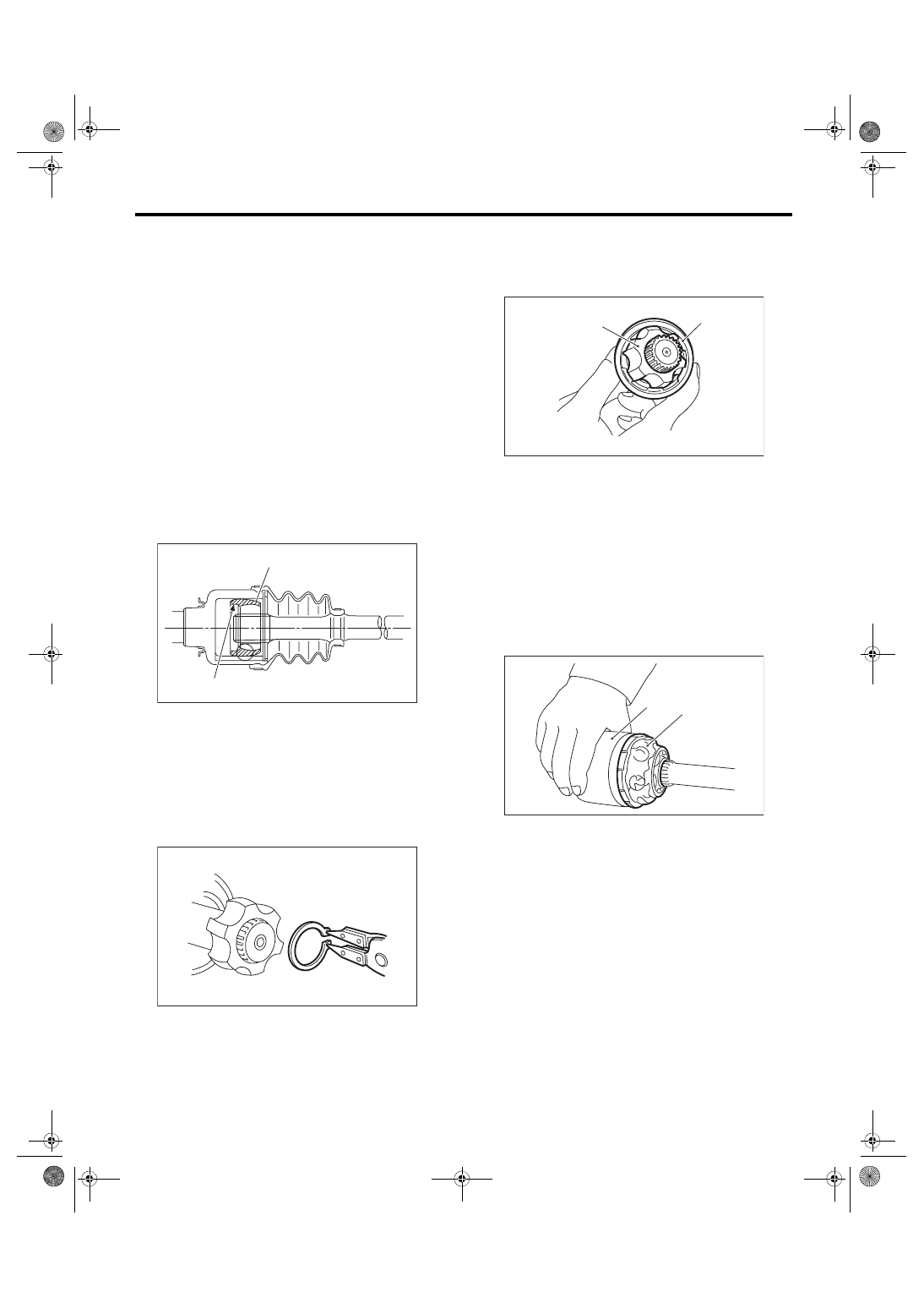
3) Insert the DOJ cage onto shaft.
NOTE:

Insert  the  cage  with  the  cutout  portion  facing  the

shaft end, since the cage has an orientation.

4) Install  the  DOJ  inner  race  on  shaft  and  fix  the

snap ring in place with pliers.
NOTE:

Confirm that the snap ring is completely fitted in the

shaft groove.

5) Install the cage to inner race fixed upon shaft.
NOTE:

Fit the cage with the protruding section aligned with

the track on the inner race, and turn by a half pitch.

6) Fill  80  to  90  g  (2.82  to  3.17  oz)  of  specified

grease into the inner side of the DOJ outer race.

7) Apply a thin coat of specified grease to the cage

pocket and ball.

8) Insert the ball bearings into the cage pocket.

9) Align the outer race track and ball positions, and

place the shaft, inner race, cage and ball bearings

in the original positions, and then fix outer race in

place.

(A) Cage
(B) Cutout portion

DS-00395

(B)

(A)

DS-00128

(A) Inner race
(B) Cage

(A) Outer race
(B) Grease

DS-00129

(B)

(A)

DS-00126

(B)

(A)

DS-42

Rear Drive Shaft

DRIVE SHAFT SYSTEM

10) Install the snap ring in the groove on the DOJ

outer race.
NOTE:

• Assure  that  the  balls,  cage  and  inner  race  are

completely fitted in the outer race of DOJ.

• Use  care  not  to  place  the  matched  position  of

snap ring in the ball groove of outer race.

• Pull the shaft lightly and assure that the circlip is

completely fitted in the groove.

11) Apply an even coat of the specified grease [20

to 30 g (0.71 to 1.06 oz)] to the entire inner surface

of boot. Also apply grease to the shaft.

12) Install the DOJ boot taking care not to twist it.
NOTE:

• The inside of the large end of DOJ boot and the

boot groove shall be cleaned so as to be free from

grease and other substances.

• When installing the DOJ boot, position the outer

race of DOJ at center of the stroke.

13) Put a new band through the clip and wind twice

in the band groove of the boot.

14) Pinch the end of band with pliers. Hold the clip

and tighten securely.
NOTE:

When tightening boot, use care so that the air with-

in the boot is appropriate.

15) Tighten the band using the ST.

ST 925091000

BAND TIGHTENING TOOL

NOTE:

Tighten the band until it cannot be moved by hand.

16) Tap the clip with the punch provided at the end

of the ST.

ST 925091000

BAND TIGHTENING TOOL

NOTE:

Tap  to  an  extent  that  the  boot  underneath  is  not

damaged.

17) Cut off the band with an allowance of about 10

mm (0.39 in) left from the clip and bend this allow-

ance over the clip.
NOTE:

Be careful so that the end of the band is in close

contact with clip.

18) Install the EBJ boot using the same procedures

as for the DOJ boot.

19) Extend and retract the DOJ repeatedly to pro-

vide an equal coating of grease.

E: INSPECTION

Check the removed parts for damage, wear, corro-

sion etc. Repair or replace if defective.

• EDJ (high-efficiency compact double offset joint)

Check  for  seizure,  corrosion,  damage,  wear  and

excessive play.

• DOJ (Double Offset Joint)

Check  for  seizure,  corrosion,  damage,  wear  and

excessive play.

• EBJ (high-efficiency compact ball fixed joint)

Check  for  seizure,  corrosion,  damage,  wear  and

excessive play.

• Shaft

Check  for  excessive  bending,  twisting,  damage

and wear.

• Boot

Check for wear, warping, breakage and scratches.

• Grease

Check for discoloration and fluidity.

DS-00125

DS-00132

DS-00133

DS-43

General Diagnostic Table

DRIVE SHAFT SYSTEM

9. General Diagnostic Table

A: INSPECTION

NOTE:

Vibration while cruising may be caused by an unbalanced tire, improper tire inflation pressure, improper

wheel alignment, etc.

Symptoms

Possible cause

Corrective action

Noise or vibration from propeller shaft Center bearing

Check the center bearing. <Ref. to DS-13, CEN-
TER BEARING FREE PLAY, INSPECTION, Pro-
peller Shaft.>

Runout of propeller shaft

Check for deflection of the propeller shaft. <Ref. 
to DS-13, RUNOUT OF PROPELLER SHAFT, 
INSPECTION, Propeller Shaft.>

Loose or gap at connections

Check the joints and connectors. <Ref. to DS-12, 
JOINTS AND CONNECTIONS, INSPECTION, 
Propeller Shaft.>
Check the spline and bearing. <Ref. to DS-12, 
SPLINES AND BEARING, INSPECTION, Pro-
peller Shaft.>

Abnormal wheel vibration

Wheel is out of balance.

Check the wheel balance. <Ref. to WT-6, 
WHEEL BALANCING, INSPECTION, Tire and 
Wheel.>

Front wheel alignment

Check the front wheel alignment. <Ref. to FS-8, 
INSPECTION, Wheel Alignment.>

Rear wheel alignment

Check the rear wheel alignment. <Ref. to RS-8, 
INSPECTION, Wheel Alignment.>

Front strut

Check the front strut. <Ref. to FS-26, INSPEC-
TION, Front Strut.>

Rear shock absorber

Check the rear shock absorber. <Ref. to RS-14, 
INSPECTION, Rear Shock Absorber.>

Front drive shaft

Check the front drive shaft. <Ref. to DS-34, 
INSPECTION, Front Drive Shaft.>

Rear drive shaft

Check the rear drive shaft. <Ref. to DS-42, 
INSPECTION, Rear Drive Shaft.>

Front hub unit bearing

Check the front hub unit bearing. <Ref. to DS-19, 
INSPECTION, Front Hub Unit Bearing.>

Rear hub unit bearing

Check the rear hub unit bearing. <Ref. to DS-26, 
INSPECTION, Rear Hub Unit Bearing.>

Noise from the underbody

Wheel is out of balance.

Check the wheel balance. <Ref. to WT-6, 
WHEEL BALANCING, INSPECTION, Tire and 
Wheel.>

Front wheel alignment

Check the front wheel alignment. <Ref. to FS-8, 
INSPECTION, Wheel Alignment.>

Rear wheel alignment

Check the rear wheel alignment. <Ref. to RS-8, 
INSPECTION, Wheel Alignment.>

Front strut

Check the front strut. <Ref. to FS-26, INSPEC-
TION, Front Strut.>

Rear shock absorber

Check the rear shock absorber. <Ref. to RS-14, 
INSPECTION, Rear Shock Absorber.>

DS-44

General Diagnostic Table

DRIVE SHAFT SYSTEM


Content   ..  515  516  517  518   ..