Subaru Impreza 3 / Impreza WRX / Impreza WRX STI. Manual - part 509
 

  Index      Subaru     Subaru Impreza 3 / Impreza WRX / Impreza WRX STI - service repair manual 2008-2014 year


Search            


Content   ..  507  508  509  510   ..


Subaru Impreza 3 / Impreza WRX / Impreza WRX STI. Manual - part 509


DS-9

General Description

DRIVE SHAFT SYSTEM

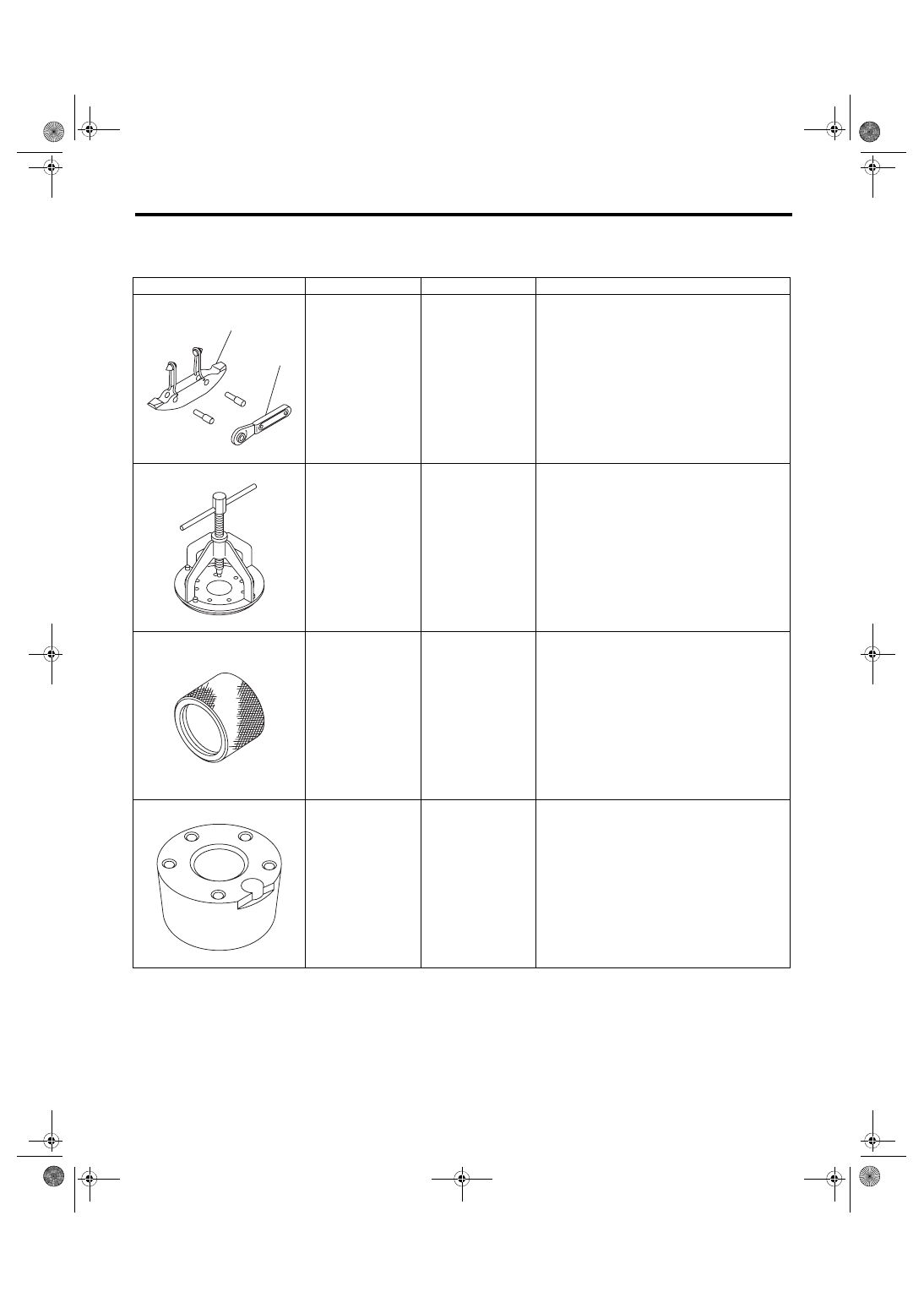
D: PREPARATION TOOL

1. SPECIAL TOOL

ILLUSTRATION

TOOL NUMBER

DESCRIPTION

REMARKS

925091000

BAND TIGHTENING 
TOOL

Used for tightening the boot band.
(A) Jig for the band
(B) Ratchet wrench

926470000

AXLE SHAFT 
PULLER

• Used for removing the axle shaft.
• Used together with AXLE SHAFT PULLER 
PLATE (28099PA110).

18675AA000

DIFFERENTIAL 
SIDE OIL SEAL 
INSTALLER

Used for installing the differential side retainer oil 
seal.

28099PA080

HUB STAND

Used for assembling hub bolt in hub.

ST-925091000

(A)

(B)

ST-926470000

ST18675AA000

ST28099PA080

DS-10

General Description

DRIVE SHAFT SYSTEM

2. GENERAL TOOL

28099PA110

AXLE SHAFT 
PULLER PLATE

Exchange with the plate of the AXLE SHAFT 
PULLER (926470000) to use.

28099PA090

OIL SEAL PROTEC-
TOR

• Used for installing the rear drive shaft to the 
rear differential.
• For protecting the oil seal.

28399SA010

OIL SEAL PROTEC-
TOR

• Used for installing front drive shaft into front 
differential.
• For protecting the oil seal.

28399AG000

HUB STAND

Used for extracting hub bolt.

TOOL NAME

REMARKS

Puller

Used for removing the ball joint from knuckle arm.

Dial gauge

Used for inspecting the propeller shaft run-out.

Extension cap

Used for preventing leakage of gear oil or ATF.

Crowbar

Used for extracting drive shaft.

ILLUSTRATION

TOOL NUMBER

DESCRIPTION

REMARKS

ST28099PA110

ST28099PA090

ST28399SA010

ST28399AG000

DS-11

Propeller Shaft

DRIVE SHAFT SYSTEM

2. Propeller Shaft

A: REMOVAL

NOTE:

• Before  removing  propeller  shaft,  wrap  metal

parts with a cloth or rubber material.

• In case of a EDJ type, wrap the metal parts at the

rubber  boot  of  center  EDJ  with  a  cloth  or  rubber

material before removing propeller shaft, as shown

in the figure. The rubber boot may be damaged due

to  interference  with  adjacent  metal  parts  while

bending the EDJ during removal.

1) Disconnect the ground cable from battery.

2) Shift the select lever or gear shift lever to neutral.

3) Release the parking brake.

4) Lift up the vehicle.

5) Remove the center exhaust pipe.

6) Remove the rear exhaust pipe and muffler.

7) Remove the heat shield cover.

8) Make alignment marks on the flange yoke and

rear differential before removal.

9) Remove  the  three  bolts  holding  the  propeller

shaft to the rear differential.

10) Remove the remaining bolt.

11) Remove the two bolts which hold center bear-

ing to vehicle body.

12) Remove the propeller shaft from transmission.
CAUTION:

• Be careful not to damage oil seals and con-

tact surface of the sleeve yoke.

• Cover the center exhaust pipe with a cloth to

keep off any oil spilled from transmission when

removing propeller shaft.
NOTE:

Use a container to catch oil flowing from propeller

shaft.

(A) Heat shield cover

DS-00239

DS-00230

(A)

(A) Alignment mark

DS-00028

(A)

DS-00141

DS-00030

DS-12

Propeller Shaft

DRIVE SHAFT SYSTEM

13) Install extension cap (A) to the transmission.
NOTE:

If extension cap (A) is not available, place vinyl bag

over opening and fasten with string to prevent gear

oil from leaking.

B: INSTALLATION

1) Insert the sleeve yoke into the transmission and

attach center bearing to body.

Tightening torque:

52 N·m (5.30 kgf-m, 38.4 ft-lb)

2) Align the alignment marks (A), and connect the

flange yoke and rear differential.

Tightening torque:

31 N·m (3.16 kgf-m, 22.9 ft-lb)

3) Install the heat shield cover.

4) Install the center exhaust pipe.

5) Install the rear exhaust pipe and muffler.

6) Lower the vehicle.

7) Connect the battery ground terminal.

C: INSPECTION

NOTE:

Do not disassemble propeller shaft. Check the fol-

lowing and replace if necessary.

• Dents or cracks on the tube surface

• Splines for deformation or abnormal wear

• Unsmooth joint operation or abnormal noise

• Center  bearing  for  free  play,  noise  or  non-

smooth operation.

• Oil seals for abnormal wear or damage

• Damaged center bearing

Check the following points with propeller shaft in-

stalled in vehicle.

1. JOINTS AND CONNECTIONS

1) Remove the center exhaust pipe.

2) Remove the heat shield cover.

3) Check  for  any  looseness  of  the  yoke  flange

mounting bolts which connect to the rear differen-

tial and center bearing bracket mounting bolts.

2. SPLINES AND BEARING

1) Remove the center exhaust pipe.

2) Remove the rear exhaust pipe and muffler.

3) Remove the heat shield cover.

4) Turn the propeller shaft by hand to see if abnor-

mal free play exists at splines. Also move yokes to

see  if  abnormal  free  play  exists  at  spiders  and

bearings.

DS-00031

(A)

DS-00141

DS-00028

(A)

DS-00035


Content   ..  507  508  509  510   ..