Subaru Impreza 3 / Impreza WRX / Impreza WRX STI. Manual - part 448
 

  Index      Subaru     Subaru Impreza 3 / Impreza WRX / Impreza WRX STI - service repair manual 2008-2014 year


Search            


Content   ..  446  447  448  449   ..


Subaru Impreza 3 / Impreza WRX / Impreza WRX STI. Manual - part 448


6MT(diag)-3

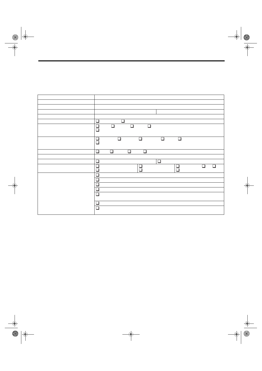
Check List for Interview

MANUAL TRANSMISSION AND DIFFERENTIAL (DIAGNOSTICS)

2. Check List for Interview

A: CHECK

Check the following items when a problem has occurred.
NOTE:

Use copies of this page for interviewing customers.

Customer’s name


Date of purchase


Date of repair


Transmission model

Transmission

V.I.N.

Odometer distance

km or miles

Frequency

 Continuous 

 Intermittent (

 times a day)

Weather

 Fine 

 Cloudy 

 Rainy 

 Snowy

 Other

(

)

Place

 Highland 

 Suburbs 

 Inner city 

 Uphill 

 Rough road

 Other

(

)

Ambient air temperature

 Hot 

 Warm 

 Cool 

 Cold

Vehicle speed

km/h (MPH)

DCCD manual mode display

 Flashing

 Other than flashing

Driving condition

 Not affected
 While decelerating

 At starting
 While accelerating

 While turning (

 RH/

 LH)

 When cruising

Symptoms

 Will not change to AUTO or MANUAL
 The forward/rear torque distribution does not change
 Will not become differential free
 Will not become differential lock
 A tight corner braking symptom occurs in AUTO mode or in MANUAL mode with differ-

ential free

 Noise or vibration
 Other

(

)

6MT(diag)-4

General Description

MANUAL TRANSMISSION AND DIFFERENTIAL (DIAGNOSTICS)

3. General Description

A: CAUTION

The airbag system wiring harness is routed near the DCCD control module.
CAUTION:

• Airbag system wiring harnesses and connectors are yellow. Do not use an electric test equipment

to check these circuits.

• Be careful not to damage the airbag system wiring harness when performing diagnostics or repair

of the DCCD control module.

• When measuring the voltage and resistance of each control module or each sensor, use a tapered

pin with a diameter of less than 0.64 mm (0.025 in) in order to avoid poor contact. Also, do not insert

the pin more than 5 mm (0.2 in) into the part.

B: INSPECTION

1. POWER SUPPLY

1) Measure the battery voltage and specific gravity of the electrolyte.
Standard voltage: 12 V or more
Specific gravity: 1.260 or more

2) Check the fuse condition.

3) Check the connecting condition of harness and harness connector.

C: PREPARATION TOOL

1. SPECIAL TOOL

2. GENERAL TOOL

ILLUSTRATION

TOOL NUMBER

DESCRIPTION

REMARKS

1B022XU0

SUBARU SELECT 
MONITOR III KIT

Troubleshooting for electrical system

TOOL NAME

REMARKS

Circuit tester

Used for measuring resistance, voltage and current.

Oscilloscope

Used for measuring the sensor.

ST1B022XU0

6MT(diag)-5

Electrical Component Location

MANUAL TRANSMISSION AND DIFFERENTIAL (DIAGNOSTICS)

4. Electrical Component Location

A: LOCATION

(1)

Engine control module (ECM)

(7)

Center differential

(12) Stop light switch

(2)

VDC control module and hydraulic 
control unit (VDCCM&H/U)

(8)

Mode change switch

(13) Rear differential oil temperature 

switch

(3)

DCCD control module

(9)

DCCD relay

(14) Data link connector

(4)

Throttle position sensor

(10) DCCD manual mode display

(15) Neutral position switch

(5)

Yaw rate & G sensor

(11) Parking brake switch

(16) Steering angle sensor

(6)

C.DIFF +/– switch


MT-02121

(1)

(3)

(4)

(5)

(6)

(2)

(7)

(8)

(9)

(15)

(13)

(10)

(11)

(12)

(14)

(16)

6MT(diag)-6

Electrical Component Location

MANUAL TRANSMISSION AND DIFFERENTIAL (DIAGNOSTICS)

MT-02338

(1)

MT-01719

(2)

(3)

MT-01720

MT-01721

(4)

MT-01722

(5)

(11)

SI-DRIVE

Sport

S

AUTO

MANU C.DIFF

SportSharp

PUSH

Intelligent

I

MT-01693

(6)

(8)

MT-01455

(7)

MT-02340

(9)

(10)

MT-02311

(12)

MT-01724


Content   ..  446  447  448  449   ..