Subaru Impreza 3 / Impreza WRX / Impreza WRX STI. Manual - part 295
EN(H4DOTC)(diag)-404
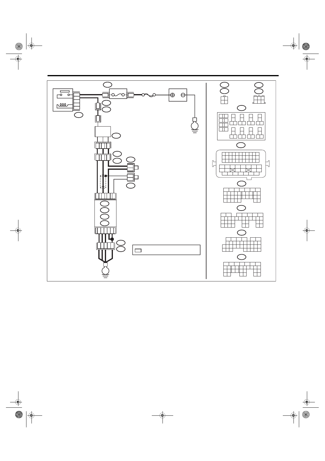
Diagnostic Procedure with Diagnostic Trouble Code (DTC)
ENGINE (DIAGNOSTICS)
ECM
6
4 5
3
2
1
*
2
1
B220
15A
9
10
11
12
B220
*
*
1 2
3 4
D1
36
D3 A4
40
34
35
B21
E2
A6
A3
B220
13
14
15 16
17
27
24
25
26
20
21
22
23
29
30
31
28
32 35
33
34
37
38
39
36
40
8
9
10
11 12
1
2
5
3
4
7
6
19
18
B134
5
6
7
8
2
1
9
4
3
10
24
22 23
25
11 12 13 14 15
26 27
28
16 17
18 19 20 21
33 34
29
32
30 31
A:
D: B137
C: B136
B: B135
A:
T6
B134
C9
B30
C20
B6
*
*
B21
1 2 3 4
12 13 14 15
5 6 7 8
16 17 18 19
9 10 11
20 21 22
23 24 25 26 27 28 29 30 31 32 33
35
34
37
36
39
38
41
40
43
42
44 45
47
46
49
48
51
50
53
52
54
4
1
3
4
1
3
B19
T5
22
T5
B19
5
6
7
8
2
1
9
4
3
10
22 23
11 12 13 14 15
24 25
26
16 17
18 19 20 21
27
28 29
30 31
B135
B:
5
6
7
8
2
1
9
4
3
10
24
22 23
25
11 12 13 14 15
26 27
28
16 17 18 19
20 21
29 30 31
32 33
34 35
B136
C:
5
6
7 8
2
1
9
4
3
10
24
22 23
25
11 12 13 14 15
26 27
28
16
17 18 19 20 21
33 34
29
32
30
31
35
D: B137
B19
T6
B83
B138
B138
B83
EN-08723
SBF-5
E
E
BATTERY
: TERMINAL No. OPTIONAL ARRANGEMENT
REAR
OXYGEN SENSOR
A/F, OXYGEN SENSOR
RELAY
FUSE
(RELAY BLOCK)