Subaru Impreza 3 / Impreza WRX / Impreza WRX STI. Manual - part 264
 

  Index      Subaru     Subaru Impreza 3 / Impreza WRX / Impreza WRX STI - service repair manual 2008-2014 year


Search            


Content   ..  262  263  264  265   ..


Subaru Impreza 3 / Impreza WRX / Impreza WRX STI. Manual - part 264


EN(H4DOTC)(diag)-280

Diagnostic Procedure with Diagnostic Trouble Code (DTC)

ENGINE (DIAGNOSTICS)

CX:DTC P050A COLD START IDLE AIR CONTROL SYSTEM PERFORMANCE

DTC DETECTING CONDITION:

• Detected when 2 consecutive driving cycles with fault occur.

• GENERAL DESCRIPTION <Ref. to GD(H4DOTC)-185, DTC P050A COLD START IDLE AIR CONTROL

SYSTEM PERFORMANCE, Diagnostic Trouble Code (DTC) Detecting Criteria.>

TROUBLE SYMPTOM:

• Engine keeps running at higher speed than specified idle speed.

• Engine keeps running at a lower speed than the specified idle speed.

• Engine stalls.
CAUTION:

After servicing or replacing faulty parts, perform Clear Memory Mode <Ref. to EN(H4DOTC)(diag)-63,

OPERATION, Clear Memory Mode.>, and Inspection Mode <Ref. to EN(H4DOTC)(diag)-49, PROCE-

DURE, Inspection Mode.>.

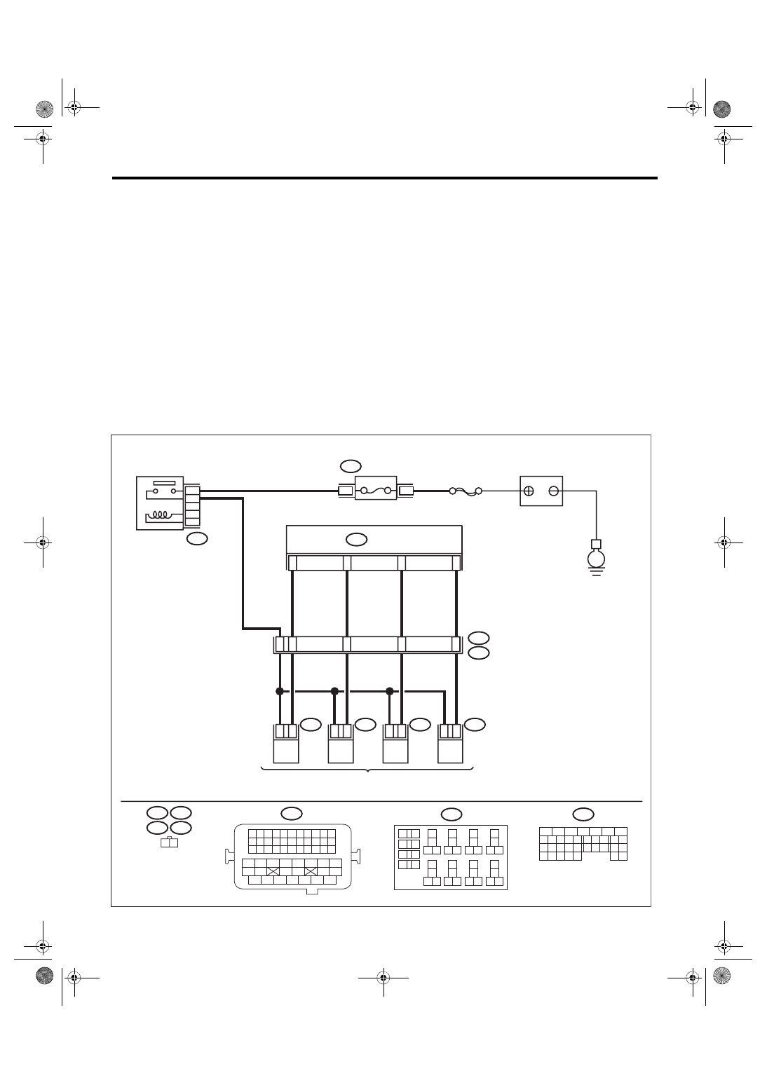
WIRING DIAGRAM:

• Engine electrical system, without SI-DRIVE <Ref. to WI-32, WITHOUT SI-DRIVE, WIRING DIAGRAM,

Engine Electrical System.>

• Engine electrical system, with SI-DRIVE <Ref. to WI-48, WITH SI-DRIVE, WIRING DIAGRAM, Engine

Electrical System.>

ECM

EN-08718

#4

2

1

#3

2

1

#2

2

1

B21

#1

2

1

4

8

54

53

52

51

10

11

12

13

1 2

B21

E5

E5

E2

E6

E6

E16

E16

E17

E17

B134

1 2 3 4

12 13 14 15

5 6 7 8

16 17 18 19

9 10 11

20 21 22

23 24 25 26 27 28 29 30 31 32 33

35

34

37

36

39

38

41

40

43

42

44 45

47

46

49

48

51

50

53

52

54

B220

24

23

22

15A

B220

3

4

21

B134

31

30

32

29

34

33

21

20

19

18

17

16

28

27

26

15

14

13

12

11

25

23

22

24

10

3

4

9

1

2

8

7

6

5

B220

18

19

6

7

4

3
5

2

1

12

11

10

9

8

40

36 39

38

37

34

33

35

32

28 31

30

29

23

22

21

20

26

25

24

27

17

16

15

14

13

E

SBF-7

MAIN RELAY

FUSE 

(RELAY BLOCK)

FUEL INJECTOR

BATTERY

EN(H4DOTC)(diag)-281

Diagnostic Procedure with Diagnostic Trouble Code (DTC)

ENGINE (DIAGNOSTICS)

Step

Check

Yes

No

1

CHECK FOR ANY OTHER DTC ON DISPLAY. Is any other DTC displayed?

Check the appropri-
ate DTC using the 
“List of Diagnostic 
Trouble Code 
(DTC)”. <Ref. to 
EN(H4DOTC)(diag)
-87, List of Diagnos-
tic Trouble Code 
(DTC).>

Go to step 

2.

2

CHECK ENGINE OIL.

Is there a proper amount of 
engine oil?

Go to step 

3.

Replace engine oil. 
<Ref. to LU(STI)-
11, REPLACE-
MENT, Engine 
Oil.>

3

CHECK EXHAUST SYSTEM.

Are there holes or loose bolts 
on exhaust system?

Repair the exhaust 
system.

Go to step 

4.

ECM

EN-08727

5

6

7

8

2

1

9

4

3

10

24

22 23

25

11 12 13 14 15

26 27

28

16 17

18 19 20 21

33 34

29

32

30 31

B136

C:

B134

A:

36

35

34

40

B17

B7

D3

A29

6

E2

B21

A1

8

C4

A2

8

6

4

25

*

*

B122

24

3

8

39

2

8

A2

A1

A19

A6

A3

D1

A4

3

E57

2

1

5

B134

B220

B220

31

29

32

A:

B137

B136

D:

C:

B135

B:

*

30

21

22

15A

B220

3

4

B135

B:

35

34

33

32

31

30

29

21

20

19

18

17

16

28

27

26

15

14

13

12

11

25

23

22

24

10

3

4

9

1

2

8

7

6

5

B220

18

19

6

7

4

3
5

2

1

12

11

10

9

8

40

36 39

38

37

34

33

35

32

28 31

30

29

23

22

21

20

26

25

24

27

17

16

15

14

13

B122

8

7

6

5

4

3

2

1

B21

33

32

31

30

29

28

27

26

47

46

45

44

43

42

54

53

52

51

50

49

48

41

40

39

38

37

36

35

34

25

24

23

22

21

20

19

18

17

16

15

14

13

12

11

10

9

8

7

6

5

4

3

2

1

D: B137

26

25

24

23

22

18

28

27

17

16

15

14

13

31

30

29

21

20

19

12

11

10

4

3

6

5

9

8

7

2

1

E57

6

5

4

3

2

1

35

34

33

32

7

26

25

24

23

22

18

28

27

17

16

15

14

13

31

30

29

21

20

19

12

11

10

4

3

6

5

9

8

2

1

E

E

E

SBF-7

FUSE 

(RELAY BLOCK)

MAIN RELAY

ELECTRONIC THROTTLE

 CONTROL RELAY

BATTERY

: TERMINAL No. OPTIONAL ARRANGEMENT

ELECTRONIC THROTTLE 

CONTROL

EN(H4DOTC)(diag)-282

Diagnostic Procedure with Diagnostic Trouble Code (DTC)

ENGINE (DIAGNOSTICS)

4

CHECK AIR INTAKE SYSTEM.

Are there holes, loose bolts or 
disconnection of hose on air 
intake system?

Repair the air 
intake system.

Go to step 

5.

5

CHECK FUEL PRESSURE.
WARNING:

Place  “NO  OPEN  FLAMES”  signs  near  the
working area.
CAUTION:

Be careful not to spill fuel.
Measure the fuel pressure while disconnecting 
pressure regulator vacuum hose from intake 
manifold. <Ref. to ME(STI)-25, INSPECTION, 
Fuel Pressure.> <Ref. to ME(w/o STI)-24, 
INSPECTION, Fuel Pressure.>
CAUTION:

Release fuel pressure before removing the
fuel pressure gauge.
NOTE:

If fuel pressure does not increase, squeeze the
fuel return hose 2 to 3 times, then measure fuel
pressure again.

Is the measured value 284 — 
314 kPa (2.9 — 3.2 kg/cm

2

, 41 

— 46 psi)?

Go to step 

6.

Check the fuel 
pump and fuel 
delivery line.
• Models without 
SI-DRIVE <Ref. to 
FU(w/o STI)-79, 
INSPECTION, 
Fuel Pump.> <Ref. 
to FU(w/o STI)-93, 
INSPECTION, 
Fuel Delivery, 
Return and Evapo-
ration Lines.>
• Models with SI-
DRIVE <Ref. to 
FU(STI)-81, 
INSPECTION, 
Fuel Pump.> <Ref. 
to FU(STI)-97, 
INSPECTION, 
Fuel Delivery, 
Return and Evapo-
ration Lines.>

6

CHECK FUEL PRESSURE.
After connecting the pressure regulator vacuum 
hose, measure fuel pressure. <Ref. to ME(STI)-
25, INSPECTION, Fuel Pressure.> <Ref. to 
ME(w/o STI)-24, INSPECTION, Fuel Pres-
sure.>
CAUTION:

Release fuel pressure before removing the
fuel pressure gauge.
NOTE:

• If fuel pressure does not increase, squeeze
fuel return hose 2 to 3 times, then measure fuel
pressure again.
• If  the  measured  value  at  this  step  is  out  of
specification, check or replace pressure regula-
tor and pressure regulator vacuum hose.

Is the measured value 230 — 
260 kPa (2.4 — 2.7 kg/cm

2

, 33 

— 38 psi)?

Go to step 

7.

Check the fuel 
pump and fuel 
delivery line.
• Models without 
SI-DRIVE <Ref. to 
FU(w/o STI)-79, 
INSPECTION, 
Fuel Pump.> <Ref. 
to FU(w/o STI)-93, 
INSPECTION, 
Fuel Delivery, 
Return and Evapo-
ration Lines.>
• Models with SI-
DRIVE <Ref. to 
FU(STI)-81, 
INSPECTION, 
Fuel Pump.> <Ref. 
to FU(STI)-97, 
INSPECTION, 
Fuel Delivery, 
Return and Evapo-
ration Lines.>

Step

Check

Yes

No

EN(H4DOTC)(diag)-283

Diagnostic Procedure with Diagnostic Trouble Code (DTC)

ENGINE (DIAGNOSTICS)

7

CHECK ENGINE COOLANT TEMPERATURE 
SENSOR.
1) Start the engine and warm up completely.
2) Read the value of «Coolant Temp.» using 
the Subaru Select Monitor or a general scan 
tool.
NOTE:

• Subaru Select Monitor
For  detailed  operation  procedures,  refer  to
“READ CURRENT DATA FOR ENGINE”. <Ref.
to EN(H4DOTC)(diag)-40, Subaru Select Moni-
tor.>
• General scan tool
For detailed operation procedures, refer to the
general scan tool operation manual.

Is the value of «Coolant 
Temp.» 75°C (167°F) or more?

Go to step 

8.

Replace the 
engine coolant 
temperature sen-
sor. <Ref. to 
FU(STI)-34, 
Engine Coolant 
Temperature Sen-
sor.> <Ref. to 
FU(w/o STI)-34, 
Engine Coolant 
Temperature Sen-
sor.>

8

CHECK MASS AIR FLOW AND INTAKE AIR 
TEMPERATURE SENSOR.
1) Start the engine and warm up engine until 
coolant temperature is higher than 75°C 
(167°F).
2) Place the shift lever in neutral position.
3) Turn the A/C switch to OFF.
4) Turn all the accessory switches to OFF.
5) Read the value of «Mass Air Flow» using 
the Subaru Select Monitor or a general scan 
tool.
NOTE:

• Subaru Select Monitor
For  detailed  operation  procedures,  refer  to
“READ CURRENT DATA FOR ENGINE”. <Ref.
to EN(H4DOTC)(diag)-40, Subaru Select Moni-
tor.>
• General scan tool
For detailed operation procedures, refer to the
general scan tool operation manual.

Is the value of «Mass Air Flow» 
2.0 — 5.0 g/s (0.26 — 0.66 lb/m)?

Go to step 

9.

Replace the mass 
air flow and intake 
air temperature 
sensor. <Ref. to 
FU(STI)-42, Mass 
Air Flow and Intake 
Air Temperature 
Sensor.> <Ref. to 
FU(w/o STI)-42, 
Mass Air Flow and 
Intake Air Temper-
ature Sensor.>

9

CHECK MASS AIR FLOW AND INTAKE AIR 
TEMPERATURE SENSOR.
1) Start the engine and warm up engine until 
coolant temperature is higher than 75°C 
(167°F).
2) Place the shift lever in neutral position.
3) Turn the A/C switch to OFF.
4) Turn all the accessory switches to OFF.
5) Open the front hood.
6) Measure the ambient temperature.
7) Read the value of «Intake Air Temp.» using 
the Subaru Select Monitor or a general scan 
tool.
NOTE:

• Subaru Select Monitor
For  detailed  operation  procedures,  refer  to
“READ CURRENT DATA FOR ENGINE”. <Ref.
to EN(H4DOTC)(diag)-40, Subaru Select Moni-
tor.>
• General scan tool
For detailed operation procedures, refer to the
general scan tool operation manual.

Subtract ambient temperature 
from «Intake Air Temp.». Is the 
obtained value –10 — 50°C (–18 
— 90°F)?

Go to step 

10.

Check the mass air 
flow and intake air 
temperature sen-
sor. <Ref. to 
FU(STI)-42, Mass 
Air Flow and Intake 
Air Temperature 
Sensor.> <Ref. to 
FU(w/o STI)-42, 
Mass Air Flow and 
Intake Air Temper-
ature Sensor.>

Step

Check

Yes

No


Content   ..  262  263  264  265   ..