Subaru Impreza 3 / Impreza WRX / Impreza WRX STI. Manual - part 257


  Index      Subaru     Subaru Impreza 3 / Impreza WRX / Impreza WRX STI - service repair manual 2008-2014 year


Search            


Content   ..  255  256  257  258   ..


Subaru Impreza 3 / Impreza WRX / Impreza WRX STI. Manual - part 257


EN(H4DOTC)(diag)-252

Diagnostic Procedure with Diagnostic Trouble Code (DTC)

ENGINE (DIAGNOSTICS)

3

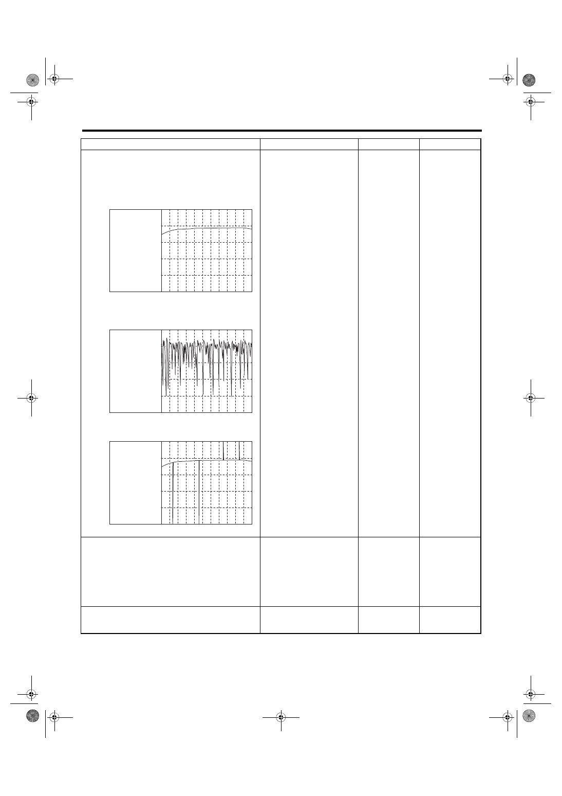
CHECK WAVEFORM DATA ON THE SUBA-
RU SELECT MONITOR (WHILE IDLING).
1) Run the engine at idle.
2) In the condition of step 1), use the Subaru 
Select Monitor to read the waveform data.
• At normal condition

• At abnormal condition 1 (numerous inver-
sion)

• At abnormal condition 2 (noise input)

Is a normal waveform dis-
played?

Go to step 

4.

• The waveform is 
displayed at abnor-
mal condition 1: Go 
to step 

4.

• The waveform is 
displayed at abnor-
mal condition 2: Go 
to step 

5.

4

CHECK CATALYTIC CONVERTER.

Is the catalytic converter dam-
aged?

Replace the cata-
lytic converter. 
<Ref. to EC(STI)-
5, Front Catalytic 
Converter.> <Ref. 
to EC(w/o STI)-5, 
Front Catalytic 
Converter.>

Go to step 

5.

5

CHECK REAR OXYGEN SENSOR CONNEC-
TOR AND COUPLING CONNECTOR.

Has water entered the connec-
tor?

Completely 
remove any water 
inside.

Go to step 

6.

Step

Check

Yes

No

EN-06668

1

0

10 sec/div

REAR OXYGEN 

SENSOR VOLTAGE 

                           (V)

EN-06669

1

0

10 sec/div

REAR OXYGEN 

SENSOR VOLTAGE 

                           (V)

EN-06670

1

0

10 sec/div

REAR OXYGEN 

SENSOR VOLTAGE 

                           (V)

EN(H4DOTC)(diag)-253

Diagnostic Procedure with Diagnostic Trouble Code (DTC)

ENGINE (DIAGNOSTICS)

6

CHECK HARNESS BETWEEN ECM AND 
REAR OXYGEN SENSOR CONNECTOR.
1) Turn the ignition switch to OFF.
2) Disconnect the connector from ECM and 
rear oxygen sensor.
3) Measure the resistance of harness between 
ECM connector and rear oxygen sensor con-
nector.

Connector & terminal

(B136) No. 20 — (T6) No. 3:
(B135) No. 30 — (T6) No. 4:

Is the resistance less than 1 Ω? Go to step 

7.

Repair the harness 
and connector.
NOTE:

Repair  the  follow-
ing locations.
• Open  circuit  in
harness  between
ECM 

connector

and  rear  oxygen
sensor connector
• Poor  contact  of
coupling connector

7

CHECK REAR OXYGEN SENSOR SHIELD.
1) Turn the ignition switch to OFF.
2) Expose the rear oxygen sensor connector 
body side harness sensor shield.
3) Measure the resistance between sensor 
shield and chassis ground.

Is the resistance less than 1 Ω? Go to step 

8.

Repair the open 
circuit of rear oxy-
gen sensor har-
ness.

8

CHECK ENGINE OIL AMOUNT AND EX-
HAUST GAS.
1) Check the engine oil amount. <Ref. to 
LU(STI)-11, INSPECTION, Engine Oil.>
2) Check exhaust gas during idling.

Does the engine oil amount 
drop or white smoke emit from 
the muffler?

Check the engine, 
and repair the 
defective part. 
<Ref. to ME(STI)-
107, INSPEC-
TION, Engine 
Trouble in Gen-
eral.> <Ref. to 
ME(w/o STI)-103, 
INSPECTION, 
Engine Trouble in 
General.>
After repairing the 
engine, replace the 
catalytic con-
verter. <Ref. to 
EX(STI)-8, Center 
Exhaust Pipe.>
After the catalytic 
converter is 
replaced, perform 
step 2 to check the 
normal waveform 
is displayed, and 
then exit the proce-
dure.

Go to step 

9.

9

CHECK IGNITION SYSTEM.
1) Check the spark plug. <Ref. to IG(STI)-5, 
INSPECTION, Spark Plug.> <Ref. to IG(w/o 
STI)-6, INSPECTION, Spark Plug.>
2) Check the status of the ignition coil connec-
tor and the spark plug terminal.

Is there any fault in the ignition 
system?

After repairing the 
ignition system, 
replace the cata-
lytic converter. 
<Ref. to EX(STI)-8, 
Center Exhaust 
Pipe.>
After the catalytic 
converter is 
replaced, perform 
step 2 to check the 
normal waveform 
is displayed, and 
then exit the proce-
dure.

Go to step 

10.

Step

Check

Yes

No

EN(H4DOTC)(diag)-254

Diagnostic Procedure with Diagnostic Trouble Code (DTC)

ENGINE (DIAGNOSTICS)

10

CHECK FUEL SYSTEM.
1) Refer to and check the items in “Insufficient 
fuel supply to fuel injector (except for “a. Fuel 
pump does not operate.”)” and “Leakage or 
blow out of fuel”. <Ref. to FU(STI)-98, INSPEC-
TION, Fuel System Trouble in General.> <Ref. 
to FU(w/o STI)-94, INSPECTION, Fuel System 
Trouble in General.>
2) Check throttle body. <Ref. to FU(STI)-15, 
INSPECTION, Throttle Body.> <Ref. to FU(w/o 
STI)-16, INSPECTION, Throttle Body.>
3) Check intake manifold. <Ref. to FU(STI)-33, 
INSPECTION, Intake Manifold.> <Ref. to FU(w/
o STI)-33, INSPECTION, Intake Manifold.>

Is there any fault in the fuel sys-
tem?

After repairing the 
fuel system, 
replace the cata-
lytic converter. 
<Ref. to EX(STI)-8, 
Center Exhaust 
Pipe.>
After the catalytic 
converter is 
replaced, perform 
step 2 to check the 
normal waveform 
is displayed, and 
then exit the proce-
dure.

Go to step 

11.

11

CHECK DTC.

Is any other DTC displayed?

Check the appropri-
ate DTC using the 
“List of Diagnostic 
Trouble Code 
(DTC)”. <Ref. to 
EN(H4DOTC)(diag)
-87, List of Diagnos-
tic Trouble Code 
(DTC).>
After checking the 
DTC, replace the 
catalytic con-
verter. <Ref. to 
EX(STI)-8, Center 
Exhaust Pipe.>
After the catalytic 
converter is 
replaced, perform 
step 2 to check the 
normal waveform 
is displayed, and 
then exit the proce-
dure.

Replace the rear 
oxygen sensor. 
<Ref. to FU(STI)-
56, Rear Oxygen 
Sensor.> <Ref. to 
FU(w/o STI)-55, 
Rear Oxygen Sen-
sor.>

Step

Check

Yes

No

EN(H4DOTC)(diag)-255

Diagnostic Procedure with Diagnostic Trouble Code (DTC)

ENGINE (DIAGNOSTICS)

CG:DTC P0441 EVAPORATIVE EMISSION CONT. SYS. INCORRECT PURGE 

FLOW

DTC DETECTING CONDITION:

• Detected when two consecutive driving cycles with fault occur.

• GENERAL DESCRIPTION <Ref. to GD(H4DOTC)-152, DTC P0441 EVAPORATIVE EMISSION CONT.

SYS. INCORRECT PURGE FLOW, Diagnostic Trouble Code (DTC) Detecting Criteria.>

TROUBLE SYMPTOM:

Improper idling
CAUTION:

After servicing or replacing faulty parts, perform Clear Memory Mode <Ref. to EN(H4DOTC)(diag)-63,

OPERATION, Clear Memory Mode.>, and Inspection Mode <Ref. to EN(H4DOTC)(diag)-49, PROCE-

DURE, Inspection Mode.>.

Step

Check

Yes

No

1

CHECK FOR ANY OTHER DTC ON DISPLAY. Is any other DTC displayed?

Check the appropri-
ate DTC using the 
“List of Diagnostic 
Trouble Code 
(DTC)”. <Ref. to 
EN(H4DOTC)(diag)
-87, List of Diagnos-
tic Trouble Code 
(DTC).>

Go to step 

2.

2

CHECK PURGE CONTROL SOLENOID 
VALVE.
Operate the purge control solenoid valve using 
the Subaru Select Monitor.
NOTE:

Refer  to  “Compulsory  Valve  Operation  Check
Mode” for more operation procedures. <Ref. to
EN(H4DOTC)(diag)-64, Compulsory Valve Op-
eration Check Mode.>

Does the purge control sole-
noid valve operate?

Go to step 

3.

Replace the purge 
control solenoid 
valve. <Ref. to 
EC(STI)-11, Purge 
Control Solenoid 
Valve.> <Ref. to 
EC(w/o STI)-11, 
Purge Control 
Solenoid Valve.>

3

CHECK EVAPORATIVE EMISSION CON-
TROL SYSTEM LINE.
1) Turn the ignition switch to OFF.
2) Check the delivery (test) mode connector is 
disconnected.

Are there holes, cracks, clog-
ging, or disconnection, miscon-
nection of hoses or pipes in 
evaporative emission control 
system?

Repair or replace 
the hoses or pipes.

Repair the poor 
contact of ECM 
connector.


Content   ..  255  256  257  258   ..