Subaru Impreza 3 / Impreza WRX / Impreza WRX STI. Manual - part 245
EN(H4DOTC)(diag)-204
Diagnostic Procedure with Diagnostic Trouble Code (DTC)
ENGINE (DIAGNOSTICS)
BJ:DTC P0327 KNOCK SENSOR 1 CIRCUIT LOW (BANK 1 OR SINGLE SEN-
SOR)
DTC DETECTING CONDITION:
• Immediately at fault recognition
• GENERAL DESCRIPTION <Ref. to GD(H4DOTC)-124, DTC P0327 KNOCK SENSOR 1 CIRCUIT LOW
(BANK 1 OR SINGLE SENSOR), Diagnostic Trouble Code (DTC) Detecting Criteria.>
TROUBLE SYMPTOM:
• Poor driving performance
• Knocking occurs
CAUTION:
After servicing or replacing faulty parts, perform Clear Memory Mode <Ref. to EN(H4DOTC)(diag)-63,
OPERATION, Clear Memory Mode.>, and Inspection Mode <Ref. to EN(H4DOTC)(diag)-49, PROCE-
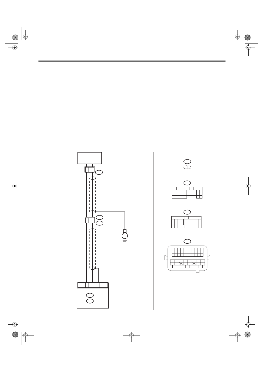
WIRING DIAGRAM:
• Engine electrical system, without SI-DRIVE <Ref. to WI-32, WITHOUT SI-DRIVE, WIRING DIAGRAM,
• Engine electrical system, with SI-DRIVE <Ref. to WI-48, WITH SI-DRIVE, WIRING DIAGRAM, Engine
ECM
EN-08730
D2
D
8
A29
B21
B137
D:
A:
31
30
29
28
27
21
20
19
18
17
16
26
25
24
15
14
13
12
11
23
22
10
3
4
9
1
2
8
7
6
5
2
1
E14
33
32
31
30
29
28
27
26
47
46
45
44
43
42
54
53
52
51
50
49
48
41
40
39
38
37
36
35
34
25
24
23
22
21
20
19
18
17
16
15
14
13
12
11
10
9
8
7
6
5
4
3
2
1
31
30
32
29
34
33
21
20
19
18
17
16
28
27
26
15
14
13
12
11
25
23
22
24
10
3
4
9
1
2
8
7
6
5
B134
E14
E2
B21
B137
B134
D:
A:
6
4
2
1
E
KNOCK SENSOR