Subaru Impreza 3 / Impreza WRX / Impreza WRX STI. Manual - part 236
 

  Index      Subaru     Subaru Impreza 3 / Impreza WRX / Impreza WRX STI - service repair manual 2008-2014 year


Search            


Content   ..  234  235  236  237   ..


Subaru Impreza 3 / Impreza WRX / Impreza WRX STI. Manual - part 236


EN(H4DOTC)(diag)-168

Diagnostic Procedure with Diagnostic Trouble Code (DTC)

ENGINE (DIAGNOSTICS)

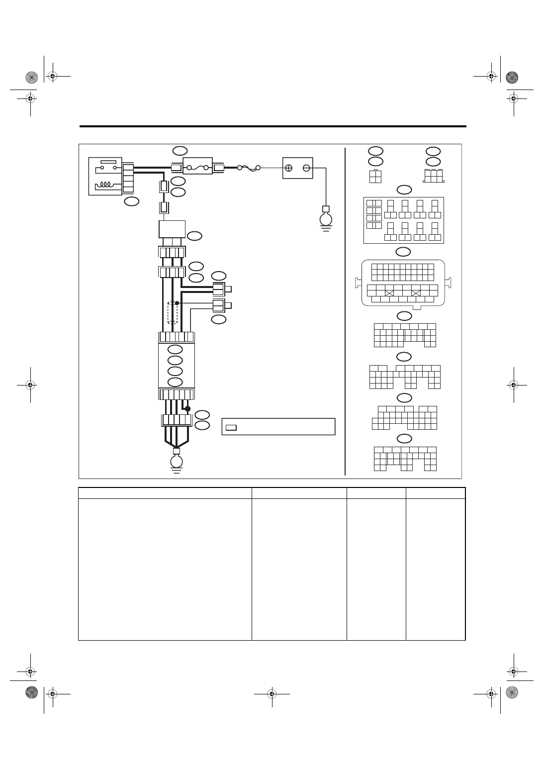
• Models with SI-DRIVE <Ref. to WI-48, WITH SI-DRIVE, WIRING DIAGRAM, Engine Electrical System.>

Step

Check

Yes

No

1

CHECK REAR OXYGEN SENSOR DATA.
1) Warm up the engine until engine coolant 
temperature is higher than 75°C (167°F), and 
keep the engine speed at 3,000 rpm. (2 minutes 
maximum)
2) Read the value of «Rear O2 Sensor» using 
the Subaru Select Monitor or a general scan 
tool.
NOTE:

• Subaru Select Monitor
For  detailed  operation  procedures,  refer  to
“READ CURRENT DATA FOR ENGINE”. <Ref.
to EN(H4DOTC)(diag)-40, Subaru Select Moni-
tor.>
• General scan tool
For detailed operation procedures, refer to the
general scan tool operation manual.

Is the value of «Rear O2 Sen-
sor» 0.490 V or more?

Go to step 

6.

Go to step 

2.

ECM

6

4 5

3

2

1

*

2

1

B220

15A

9

10

11
12

B220

*

*

1 2
3 4

D1

36

D3 A4

40

34

35

B21

E2

A6

A3

B220

13
14

15 16

17

27

24

25
26

20

21
22

23

29
30

31

28

32 35

33
34

37
38

39

36

40

8

9

10

11 12

1

2

5

3

4

7

6

19

18

B134

5

6

7

8

2

1

9

4

3

10

24

22 23

25

11 12 13 14 15

26 27

28

16 17

18 19 20 21

33 34

29

32

30 31

A:

D: B137

C: B136

B: B135

A:

T6

B134

C9

B30

C20

B6

*

*

B21

1 2 3 4

12 13 14 15

5 6 7 8

16 17 18 19

9 10 11

20 21 22

23 24 25 26 27 28 29 30 31 32 33

35

34

37

36

39

38

41

40

43

42

44 45

47

46

49

48

51

50

53

52

54

4

1

3

4

1

3

B19

T5

22

T5

B19

5

6

7

8

2

1

9

4

3

10

22 23

11 12 13 14 15

24 25

26

16 17

18 19 20 21

27

28 29

30 31

B135

B:

5

6

7

8

2

1

9

4

3

10

24

22 23

25

11 12 13 14 15

26 27

28

16 17 18 19

20 21

29 30 31

32 33

34 35

B136

C:

5

6

7 8

2

1

9

4

3

10

24

22 23

25

11 12 13 14 15

26 27

28

16

17 18 19 20 21

33 34

29

32

30

31

35

D: B137

B19

T6

B83

B138

B138

B83

EN-08723

SBF-5

E

E

BATTERY

: TERMINAL No. OPTIONAL ARRANGEMENT

REAR 

OXYGEN SENSOR

A/F, OXYGEN SENSOR 

RELAY

FUSE 

(RELAY BLOCK)

EN(H4DOTC)(diag)-169

Diagnostic Procedure with Diagnostic Trouble Code (DTC)

ENGINE (DIAGNOSTICS)

AN:DTC P0141 O2 SENSOR HEATER CIRCUIT (BANK1 SENSOR2)

For the diagnostic procedure, refer to DTC P0037. <Ref. to EN(H4DOTC)(diag)-113, DTC P0037 HO2S

HEATER CONTROL CIRCUIT LOW (BANK 1 SENSOR 2), Diagnostic Procedure with Diagnostic Trouble

Code (DTC).>

2

CHECK REAR OXYGEN SENSOR DATA.
1) Warm up the engine until engine coolant 
temperature is higher than 75°C (167°F), and 
rapidly reduce the engine speed from 3,000 
rpm.
2) Read the value of «Rear O2 Sensor» using 
the Subaru Select Monitor or a general scan 
tool.
NOTE:

• Subaru Select Monitor
For detailed operation procedures, refer to “READ
CURRENT  DATA  FOR  ENGINE”.  <Ref.  to
EN(H4DOTC)(diag)-40, Subaru Select Monitor.>
• General scan tool
For detailed operation procedures, refer to the
general scan tool operation manual.

Is the value of «Rear O2 Sen-
sor» 0.250 V or less?

Go to step 

6.

Go to step 

3.

3

CHECK REAR OXYGEN SENSOR CONNEC-
TOR AND COUPLING CONNECTOR.

Has water entered the connec-
tor?

Completely 
remove any water 
inside.

Go to step 

4.

4

CHECK HARNESS BETWEEN ECM AND 
REAR OXYGEN SENSOR CONNECTOR.
1) Turn the ignition switch to OFF.
2) Disconnect the connector from ECM and 
rear oxygen sensor.
3) Measure the resistance of harness between 
ECM connector and rear oxygen sensor con-
nector.

Connector & terminal

(B136) No. 20 — (T6) No. 3:
(B135) No. 30 — (T6) No. 4:

Is the resistance less than 1 Ω? Go to step 

5.

Repair the harness 
and connector.
NOTE:

In this case, repair
the following item:
• Open  circuit  in
harness  between
ECM 

connector

and  rear  oxygen
sensor connector
• Poor  contact  of
coupling connector

5

CHECK HARNESS BETWEEN ECM AND 
REAR OXYGEN SENSOR CONNECTOR.
1) Connect the connector to ECM.
2) Turn the ignition switch to ON.
3) Measure the voltage between rear oxygen 
sensor connector and chassis ground.

Connector & terminal

(T6) No. 3 (+) — Chassis ground (–):

Is the voltage 0.2 — 0.5 V?

Replace the rear 
oxygen sensor. 
<Ref. to FU(STI)-
56, Rear Oxygen 
Sensor.> <Ref. to 
FU(w/o STI)-55, 
Rear Oxygen Sen-
sor.>

Repair the harness 
and connector.
NOTE:

In this case, repair
the following item:
• Open  circuit  in
harness  between
ECM 

connector

and  rear  oxygen
sensor connector
• Poor  contact  of
ECM connector
• Poor  contact  of
coupling connector

6

CHECK EXHAUST SYSTEM.
Check exhaust system parts.
NOTE:

Check the following items.
• Looseness  and  improper  fitting  of  exhaust
system parts
• Damage (crack, hole etc.) of parts
• Loose part and  improper installation  between
front oxygen (A/F) sensor and rear oxygen sensor

Is there any fault in exhaust 
system?

Repair or replace 
faulty parts.

Replace the rear 
oxygen sensor. 
<Ref. to FU(STI)-
56, Rear Oxygen 
Sensor.> <Ref. to 
FU(w/o STI)-55, 
Rear Oxygen Sen-
sor.>

Step

Check

Yes

No

EN(H4DOTC)(diag)-170

Diagnostic Procedure with Diagnostic Trouble Code (DTC)

ENGINE (DIAGNOSTICS)

AO:DTC P014C O2 SENSOR SLOW RESPONSE - RICH TO LEAN (BANK 1 SEN-

SOR 1)

DTC DETECTING CONDITION:

• Detected when two consecutive driving cycles with fault occur.

• GENERAL DESCRIPTION <Ref. to GD(H4DOTC)-88, DTC P014C O2 SENSOR SLOW RESPONSE -

RICH TO LEAN (BANK 1 SENSOR 1), Diagnostic Trouble Code (DTC) Detecting Criteria.>
CAUTION:

After servicing or replacing faulty parts, perform Clear Memory Mode <Ref. to EN(H4DOTC)(diag)-63,

OPERATION, Clear Memory Mode.>, and Inspection Mode <Ref. to EN(H4DOTC)(diag)-49, PROCE-

DURE, Inspection Mode.>.

AP:DTC P014D O2 SENSOR SLOW RESPONSE - LEAN TO RICH (BANK 1 SEN-

SOR 1)

NOTE:

For the diagnostic procedure, refer to DTC P014C. <Ref. to EN(H4DOTC)(diag)-170, DTC P014C O2 SEN-

SOR SLOW RESPONSE - RICH TO LEAN (BANK 1 SENSOR 1), Diagnostic Procedure with Diagnostic

Trouble Code (DTC).>

AQ:DTC P015A O2 SENSOR DELAYED RESPONSE - RICH TO LEAN (BANK 1 

SENSOR 1)

NOTE:

For the diagnostic procedure, refer to DTC P014C. <Ref. to EN(H4DOTC)(diag)-170, DTC P014C O2 SEN-

SOR SLOW RESPONSE - RICH TO LEAN (BANK 1 SENSOR 1), Diagnostic Procedure with Diagnostic

Trouble Code (DTC).>

AR:DTC P015B O2 SENSOR DELAYED RESPONSE - LEAN TO RICH (BANK 1 

SENSOR 1)

NOTE:

For the diagnostic procedure, refer to DTC P014C. <Ref. to EN(H4DOTC)(diag)-170, DTC P014C O2 SEN-

SOR SLOW RESPONSE - RICH TO LEAN (BANK 1 SENSOR 1), Diagnostic Procedure with Diagnostic

Trouble Code (DTC).>

AS:DTC P0171 SYSTEM TOO LEAN (BANK 1)

For the diagnostic procedure, refer to DTC P0172. <Ref. to EN(H4DOTC)(diag)-171, DTC P0172 SYSTEM

TOO RICH (BANK 1), Diagnostic Procedure with Diagnostic Trouble Code (DTC).>

Step

Check

Yes

No

1

CHECK EXHAUST SYSTEM.
NOTE:

Check the following items.
• Loose installation of front portion of exhaust
pipe onto cylinder heads
• Loose connection between front exhaust pipe
and front catalytic converter
• Damage of exhaust pipe resulting in a hole

Is there any fault in exhaust 
system?

Repair the exhaust 
system.

Replace the front 
oxygen (A/F) sen-
sor. <Ref. to 
FU(STI)-54, Front 
Oxygen (A/F) Sen-
sor.> <Ref. to 
FU(w/o STI)-53, 
Front Oxygen (A/F) 
Sensor.>

EN(H4DOTC)(diag)-171

Diagnostic Procedure with Diagnostic Trouble Code (DTC)

ENGINE (DIAGNOSTICS)

AT:DTC P0172 SYSTEM TOO RICH (BANK 1)

DTC DETECTING CONDITION:

• Detected when 2 consecutive driving cycles with fault occur.

• GENERAL DESCRIPTION <Ref. to GD(H4DOTC)-99, DTC P0172 SYSTEM TOO RICH (BANK 1), Diag-

nostic Trouble Code (DTC) Detecting Criteria.>

TROUBLE SYMPTOM:

• Improper idling

• Engine stalls.

• Poor driving performance
CAUTION:

After servicing or replacing faulty parts, perform Clear Memory Mode <Ref. to EN(H4DOTC)(diag)-63,

OPERATION, Clear Memory Mode.>, and Inspection Mode <Ref. to EN(H4DOTC)(diag)-49, PROCE-

DURE, Inspection Mode.>.

Step

Check

Yes

No

1

CHECK EXHAUST SYSTEM.

Are there holes or loose bolts 
on exhaust system?

Repair the exhaust 
system.

Go to step 

2.

2

CHECK AIR INTAKE SYSTEM.

Are there holes, loose bolts or 
disconnection of hose on air 
intake system?

Repair the air 
intake system.

Go to step 

3.

3

CHECK FUEL PRESSURE.
WARNING:

Place  “NO  OPEN  FLAMES”  signs  near  the
working area.
CAUTION:

Be careful not to spill fuel.
Measure the fuel pressure while disconnecting 
pressure regulator vacuum hose from intake 
manifold. <Ref. to ME(STI)-25, INSPECTION, 
Fuel Pressure.> <Ref. to ME(w/o STI)-24, 
INSPECTION, Fuel Pressure.>
CAUTION:

Release fuel pressure before removing the
fuel pressure gauge.
NOTE:

If fuel pressure does not increase, squeeze the
fuel return hose 2 to 3 times, then measure fuel
pressure again.

Is the measured value 284 — 
314 kPa (2.9 — 3.2 kg/cm

2

, 41 

— 46 psi)?

Go to step 

4.

Check the fuel 
pump and fuel 
delivery line.
• Models without 
SI-DRIVE <Ref. to 
FU(w/o STI)-79, 
INSPECTION, 
Fuel Pump.> <Ref. 
to FU(w/o STI)-93, 
INSPECTION, 
Fuel Delivery, 
Return and Evapo-
ration Lines.>
• Models with SI-
DRIVE <Ref. to 
FU(STI)-81, 
INSPECTION, 
Fuel Pump.> <Ref. 
to FU(STI)-97, 
INSPECTION, 
Fuel Delivery, 
Return and Evapo-
ration Lines.>


Content   ..  234  235  236  237   ..