Subaru Impreza 3 / Impreza WRX / Impreza WRX STI. Manual - part 204
EN(H4DOTC)(diag)-40
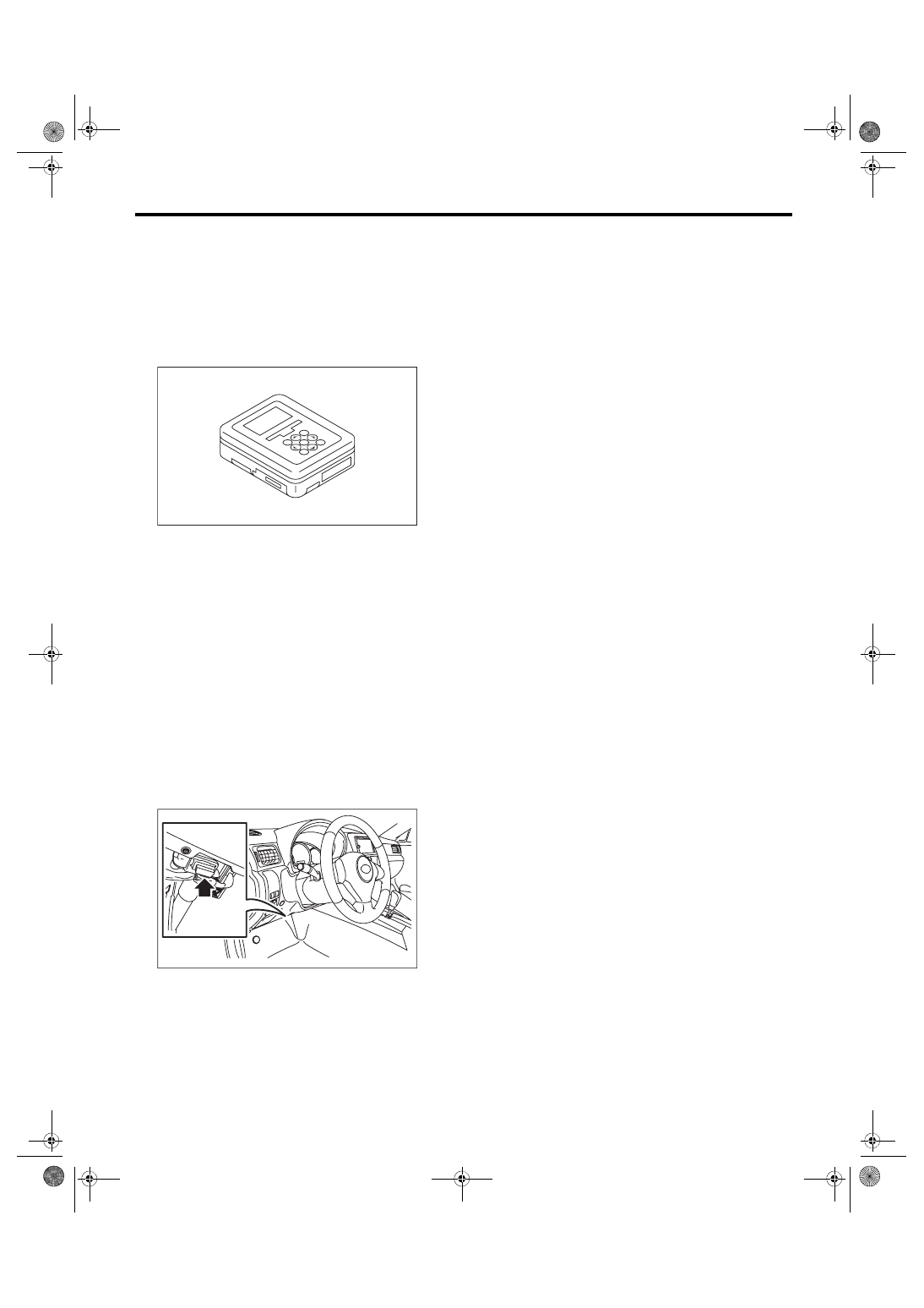
Subaru Select Monitor
ENGINE (DIAGNOSTICS)
9. Subaru Select Monitor
A: OPERATION
1. HOW TO USE SUBARU SELECT MONI-
TOR
1) Prepare the Subaru Select Monitor kit. <Ref. to
EN(H4DOTC)(diag)-8, PREPARATION TOOL,
2) Prepare PC with Subaru Select Monitor in-
stalled.
3) Connect the USB cable to SDI (Subaru Diagno-
sis Interface) and USB port on the personal com-
puter (dedicated port for the Subaru Select
Monitor).
NOTE:
The dedicated port for the Subaru Select Monitor
means the USB port which was used to install the
Subaru Select Monitor.
4) Connect the diagnosis cable to SDI.
5) Connect SDI to data link connector located in the
lower portion of the instrument panel (on the driv-
er’s side).
CAUTION:
Do not connect the scan tools except for Suba-
ru Select Monitor and general scan tool.
6) Start the PC.
7) Turn the ignition switch to ON (engine OFF) and
run the “PC application for Subaru Select Monitor”.
8) Call up DTC and data, then record them.
NOTE:
For detailed operation procedures, refer to “PC ap-
plication help for Subaru Select Monitor”.
EN-05692
EN-06148