Subaru Impreza 3 / Impreza WRX / Impreza WRX STI. Manual - part 200
EN(H4DOTC)(diag)-24
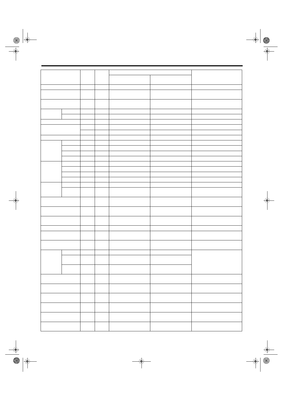
Engine Control Module (ECM) I/O Signal
ENGINE (DIAGNOSTICS)
Ignition switch
B136
30
10 — 13
12 — 14
—
Neutral position switch
B136
35
ON: 0
OFF: 10 — 13
ON: 0
OFF: 12 — 14
—
Delivery (test) mode
connector
B136
34
10 — 13
13 — 14
When connected: 0
Knock sen-
sor
Signal
B137
2
2.45 — 2.55
2.45 — 2.55
—
Shield
B137
8
0
0
—
Back-up power supply
B136
2
10 — 13
12 — 14
Ignition switch “OFF”: 10 — 13
Control module power
supply
B136
1
10 — 13
12 — 14
—
B137
7
10 — 13
12 — 14
—
Sensor power supply
B134
19
5
5
—
Ignition
control
#1
B134
21
0
0 or 5
Waveform
#2
B134
22
0
0 or 5
Waveform
#3
B134
31
0
0 or 5
Waveform
#4
B134
32
0
0 or 5
Waveform
Fuel injec-
tor
#1
B134
10
10 — 13
1 — 14
Waveform
#2
B134
11
10 — 13
1 — 14
Waveform
#3
B134
12
10 — 13
1 — 14
Waveform
#4
B134
13
10 — 13
1 — 14
Waveform
Fuel pump
control unit
Control
B136
33
0 or 5
0 or 5
Waveform
Diagnos-
tic signal
B135
10
10 — 13
12 — 14
—
A/C relay control
B135
35
ON: 0.5 or less
OFF: 10 — 13
ON: 0.5 or less
OFF: 12 — 14
—
Main fan relay control
B135
12
ON: 0.5 or less
OFF: 10 — 13
ON: 0.5 or less
OFF: 12 — 14
—
Sub fan relay control
B135
11
ON: 0.5 or less
OFF: 10 — 13
ON: 0.5 or less
OFF: 12 — 14
—
Engine speed output
B135
15
—
0 — 13 or more
Waveform
Purge control solenoid
valve 1
B137
6
ON: 1 or less
OFF: 10 — 13
ON: 1 or less
OFF: 12 — 14
Waveform
Purge control solenoid
valve 2
B137
15
ON: 1 or less
OFF: 10 — 13
ON: 1 or less
OFF: 12 — 14
Waveform
Manifold
absolute
pressure
sensor
Signal
B137
20
1.7 — 2.4
1.1 — 1.6
—
Power
supply
B134
19
5
5
Ground
(sensor)
B134
29
0
0
Power steering oil pres-
sure switch
B137
28
10 — 13
ON: 0
OFF: 12 — 14
—
SSM/GST communica-
tion line
B135
14
1 or less ←→ 4 or more
1 or less ←→ 4 or more
—
Intake camshaft posi-
tion sensor (LH)
B137
16
0 or 5
0 or 5
Waveform
Intake camshaft posi-
tion sensor (RH)
B137
24
0 or 5
0 or 5
Waveform
Exhaust camshaft posi-
tion sensor (LH)
B137
29
0 or 5
0 or 5
Models with SI-DRIVE
Waveform
Exhaust camshaft posi-
tion sensor (RH)
B137
23
0 or 5
0 or 5
Models with SI-DRIVE
Waveform
Description
Con-
nector
No.
Termi-
nal No.
Signal (V)
Note
Ignition SW ON
(engine OFF)
Engine ON
(idling)